Your part has some problems.
Breadboard
“path2” needs to be in “breadboard”
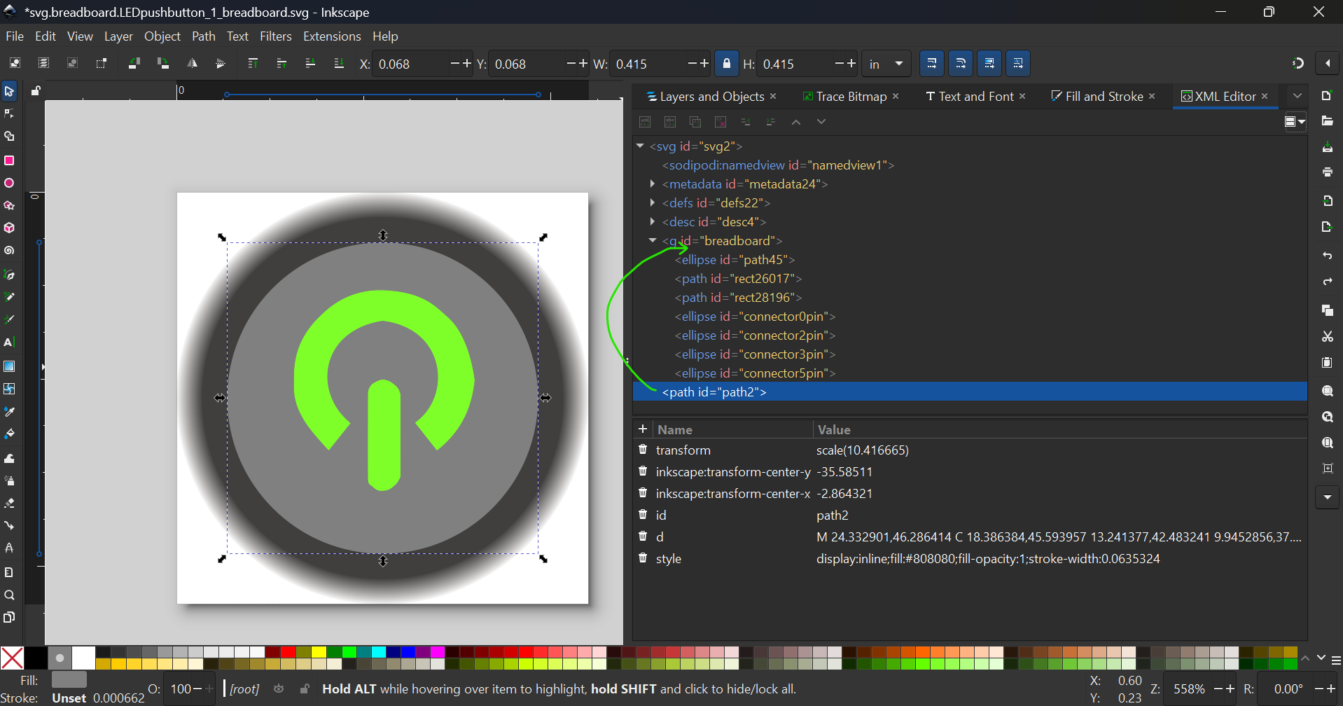
“path45” must be solid fill (or it will not export correctly in SVG format)
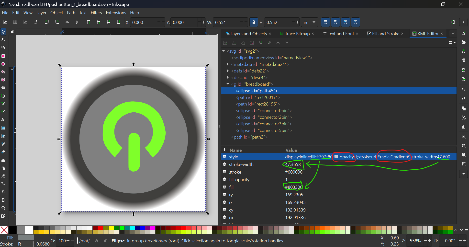
Also, make it a good habit to define fills with XML editor, here I’ve deleted the style property and filled in correct values

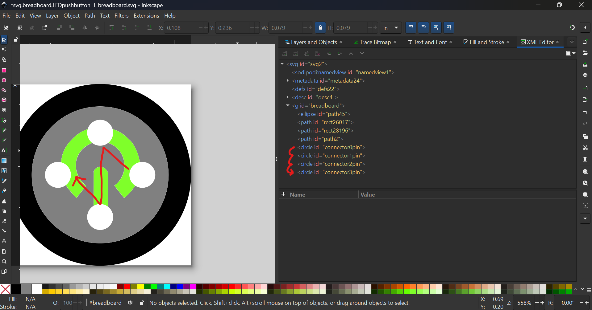
This should be what it should look like after edits
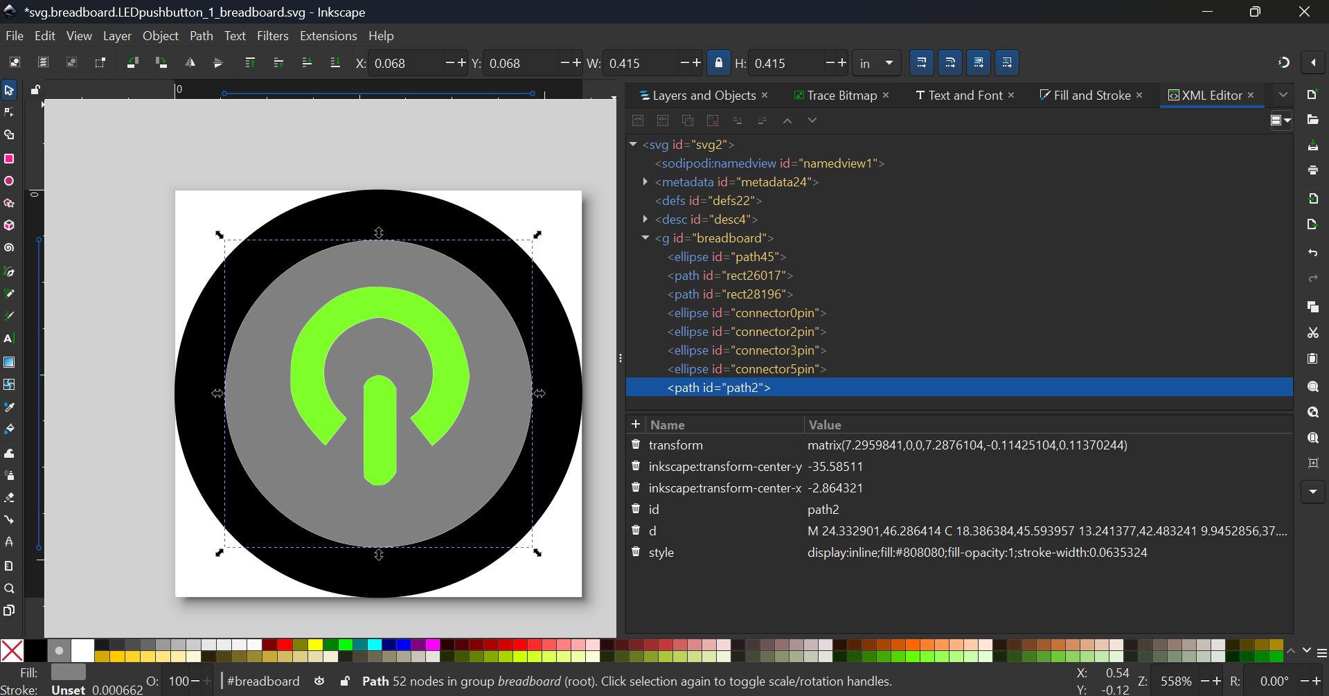
Delete these 2 properties (the Inkscape transforms)
Then ungroup (ctrl+shift+g) and regroup (ctrl+g) to remove the transforms
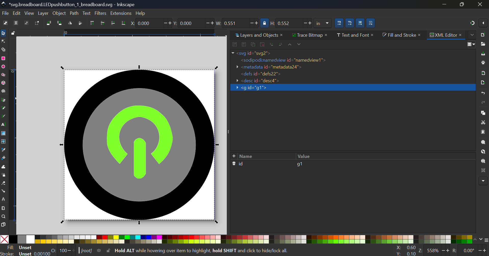
Change the ID to “breadboard”
With the schematic extension in mind, change the pin numbering from
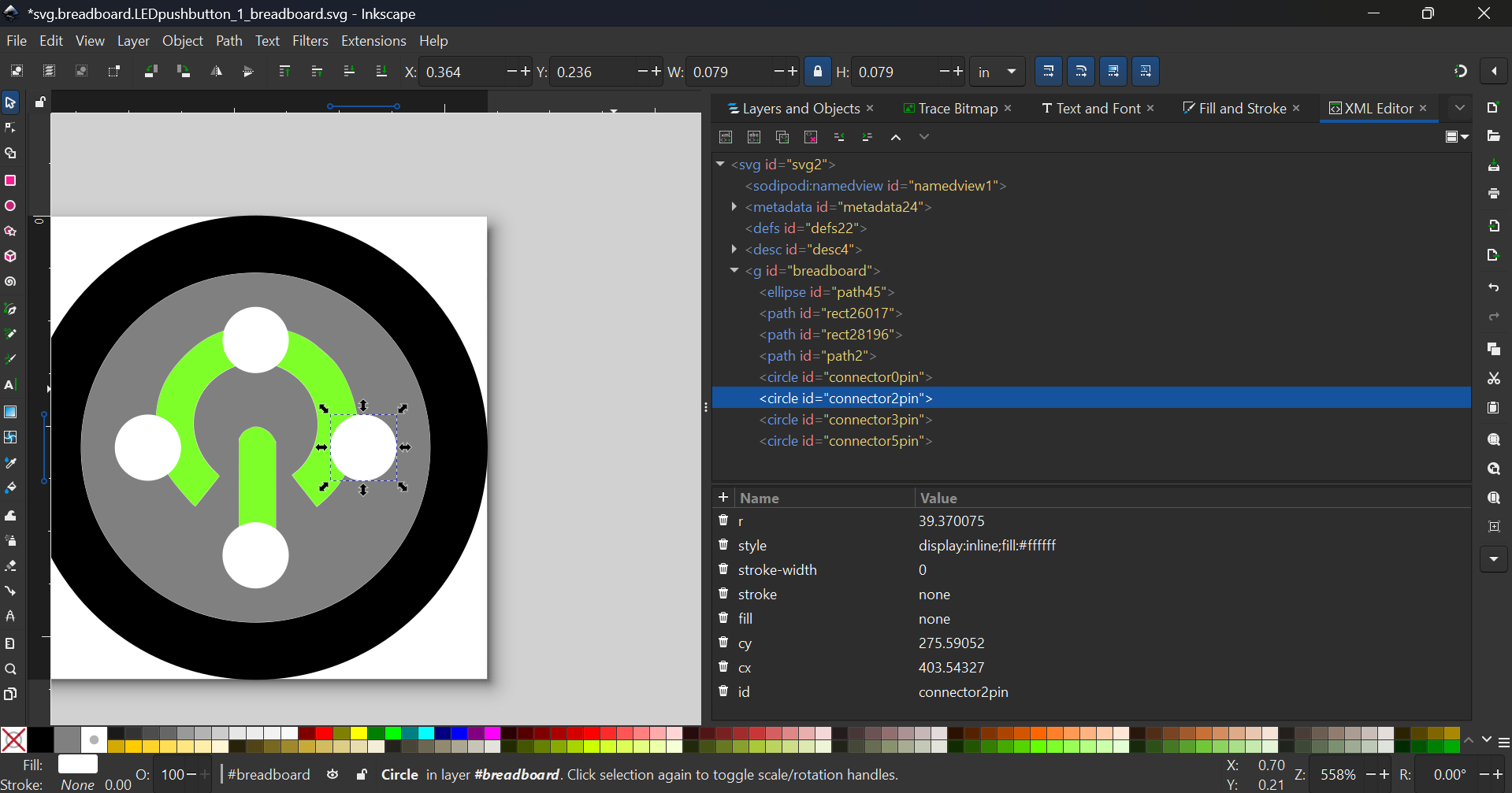
to
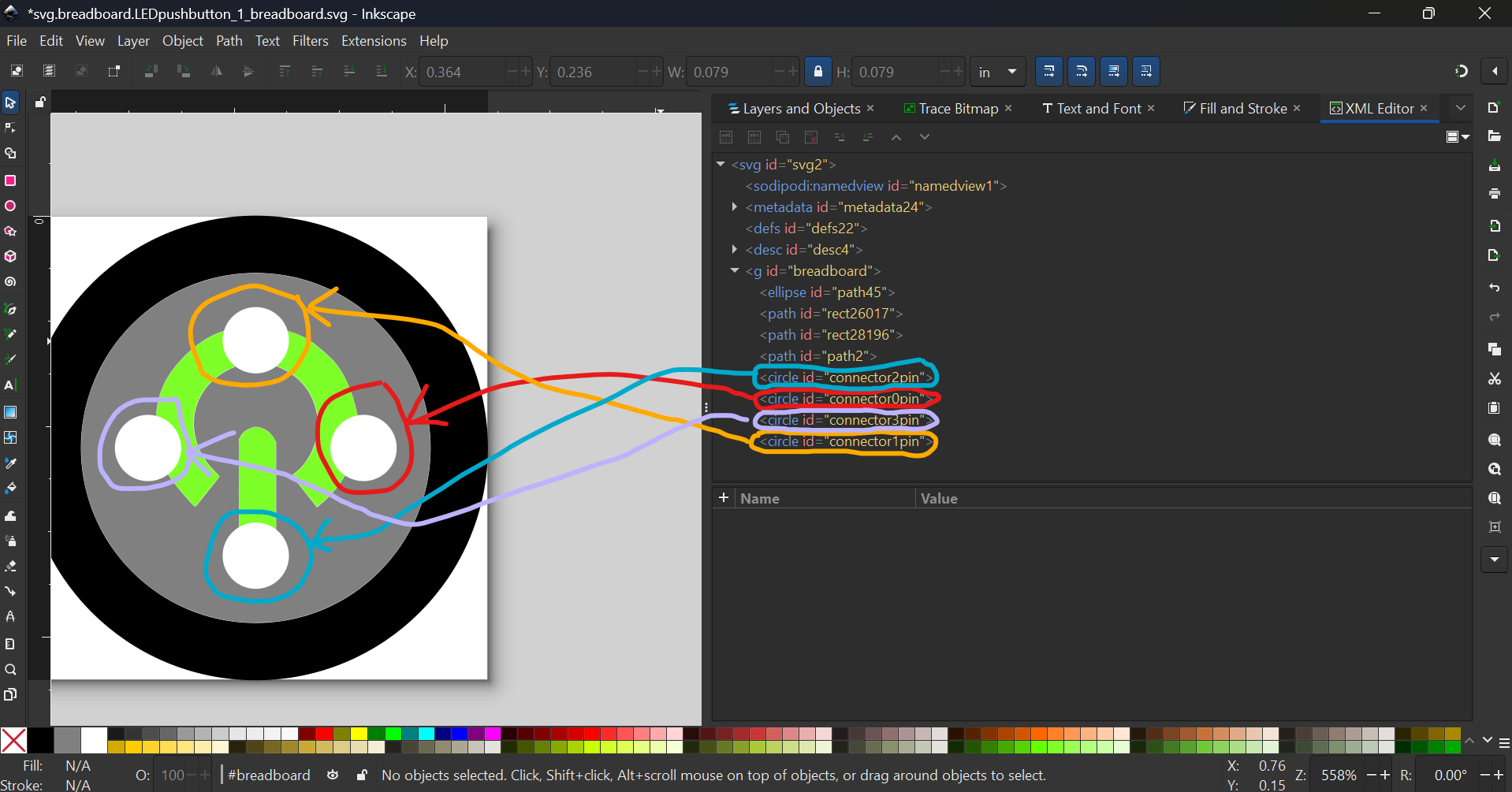
Note: For illustration purposes only, I’ve changed the fill of the connectors. Please do not do so
After all these edits, you should get this (right-click → save image as… to download this SVG)

Schematic
More problems here. Labels all wrong, and pins align to the centre (I.e. no terminalIDs)
I have fixed it in this new improved part
PCB view
You will have to redo the PCB yourself (as I do not know the dimensions of the holes of the connectors, and the objects are ellipses – they have to be circles, so that has to be redone
Instructions here, jump to PCB section.
Hope this helps
Illuminated Pushbutton-improved more.fzpz (the file is found in later posts)
Note that I did not change the ModuleID, so please delete the old part to prevent confusion
Most edits are done with the new part editor (using a 4-pin IC as a base), so to change the PCB right-click the “Illumin” chip → edit → PCB → File → Load image for view → select file → open