Hi, i finding 5V 2 Relay Module Part. Download and imported but PCB error. Please help me consider it and fix it
It would be necessary to know what part you are referring to to do pretty much anything useful.
Peter
Hi peter,
This is module 5V Dual-Channel Relay Module - Pinout, Specification, Application, Working, Datasheet
And this part had problem need fix: ArduinoDersleri/Fritzing/2-Channel 5v Relay Shield/2-Channel 5v Relay Shield.fzpz at master · GungorYalcin/ArduinoDersleri · GitHub
Thanks Peter!
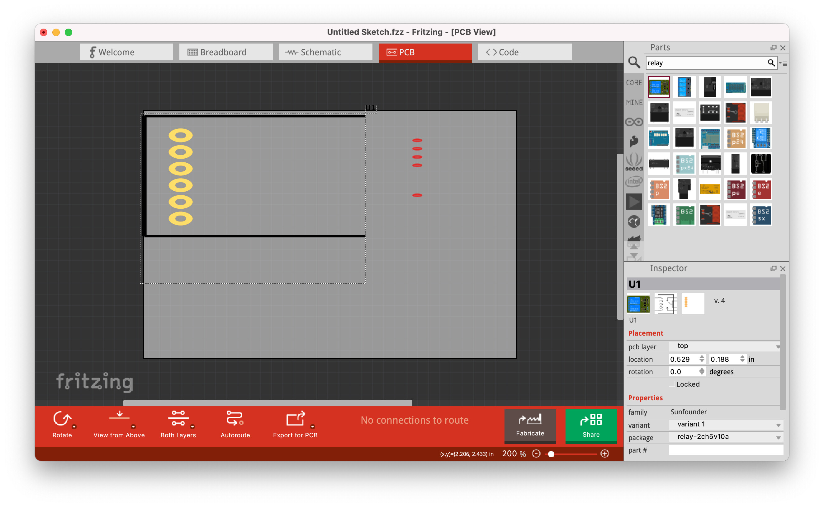
This part should do what you want. Pcb view has been suppressed as not useful (you can’t mount this on a pcb.)
edit:
Replace part with one with a partial pcb (only the 4 input pins.)
2-Channel 5v Relay Shield-fixed.fzpz (8.7 KB)
Peter
Thanks Peter for support,
I need it for my PCB. I want to create a simple circuit and mount that module on it. Could you help me fix the issue with the PCB part instead of suppressing it?
I can but the connections will be beyond the edges of the board as they won’t connect directly to the pcb unless you unsolder the headers and screw terminals. Are you intending to unsolder the terminals and headers and use wires connected from your pcb in to the board? Or are off board connectors acceptable?
Peter
I agree.I plan to solder the GPIO pins of this module directly onto my PCB and keep relay on module!
Please help me do that!
Thanks Peter!
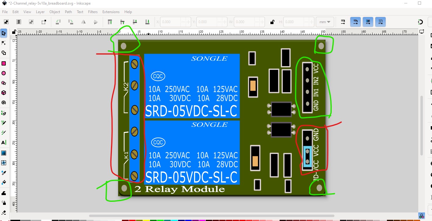
So you only want the 4 pins circled in green (and the board outline) to appear in pcb?
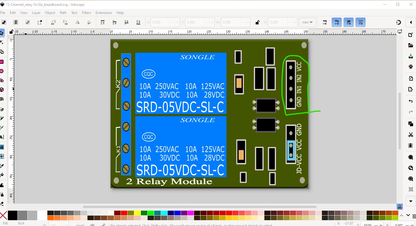
the jumpers and screw terminals will remain on the module?
edit
and the 4 mounting holes as well although they will be silkscreen only for positioning?
Peter
This doesn’t appear to be the part that I changed. It is only two channels and has less pins. To do something with this I would either need a part or a web site with physical dimensions and connections to find an existing part or make one if there isn’t one yet. A google search of the form “fritzing part 4 channel relay module” will find existing parts (there are some I think.)
Peter
Sorry my english not well. This is dimensions and connections of dual module relay. I searched on Google and found a similar 2-relay module, but it has a PCB issue. I just hope you can fix it.
I think this is my problem for not reading carefully enough.
I missed this part. That the new image is a 4 channel module but you want the two channel one I changed. So my question is what are you looking for in connections to your pcb? What makes sense to me is this
pcb will contain the 4 I/O pins circled in green, the board outline and the 4 mounting holes (only on silkscreen, you need to drag holes in to the sketch to get the holes.) The screw terminals and the jumpers remain on the relay module itself and don’t appear in pcb view.The load will attach to the screw terminals on the relay board itself via the existing screw terminals as to me that makes the most sense, but I’m not sure that is what you want. I can easily enough do a pcb the way I am thinking and see if that suits what you need and perhaps that is the best way forward. I’ll make a part as I am suggesting and see if that suits what you need.
Peter
Thank you for the detailed explanation. I agree with your approach, and connecting the load via the existing screw terminals on the relay module makes sense. Please go ahead and create the PCB as you suggested, please help me draw green and red pin in pcb. Thank you very much!
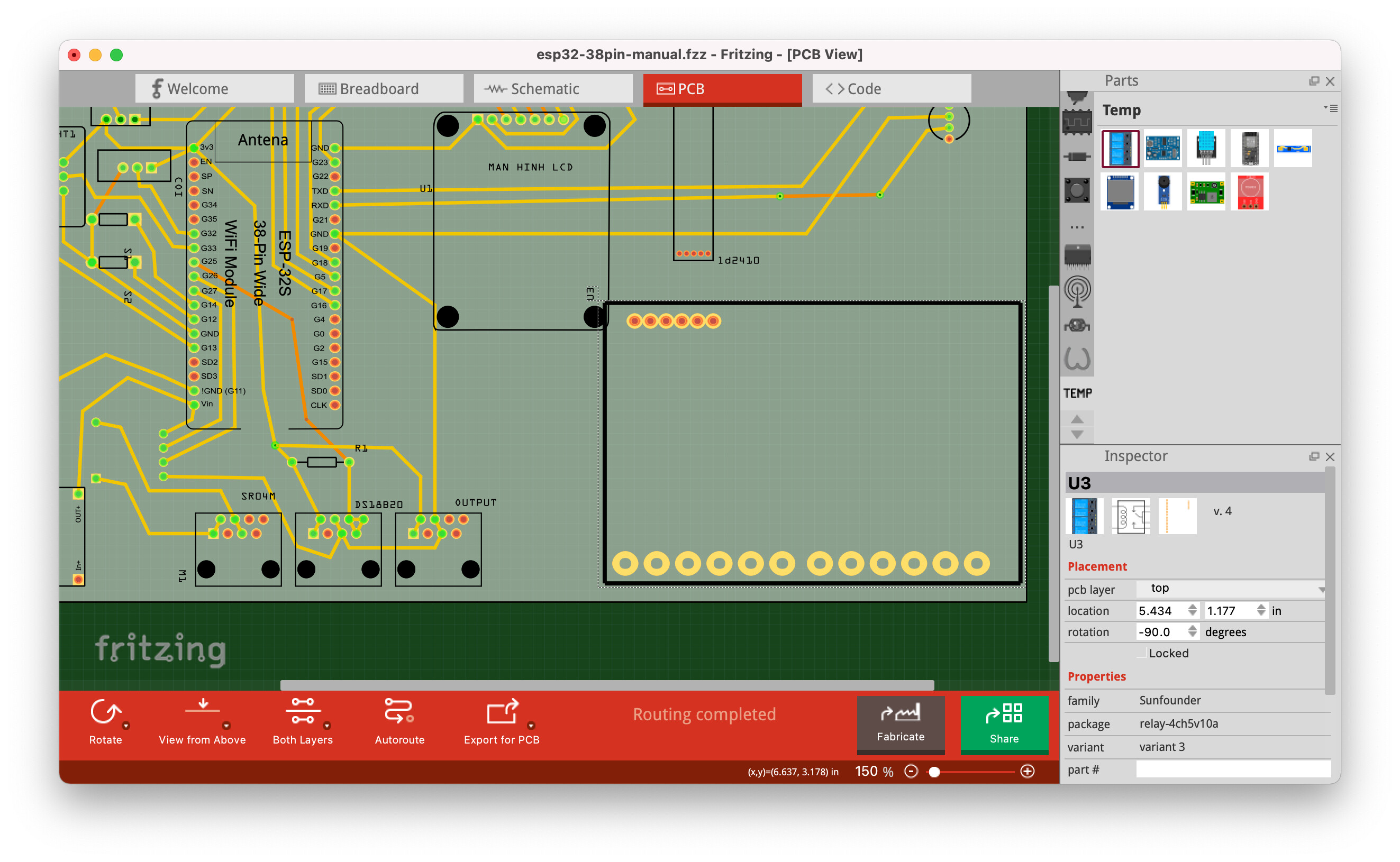
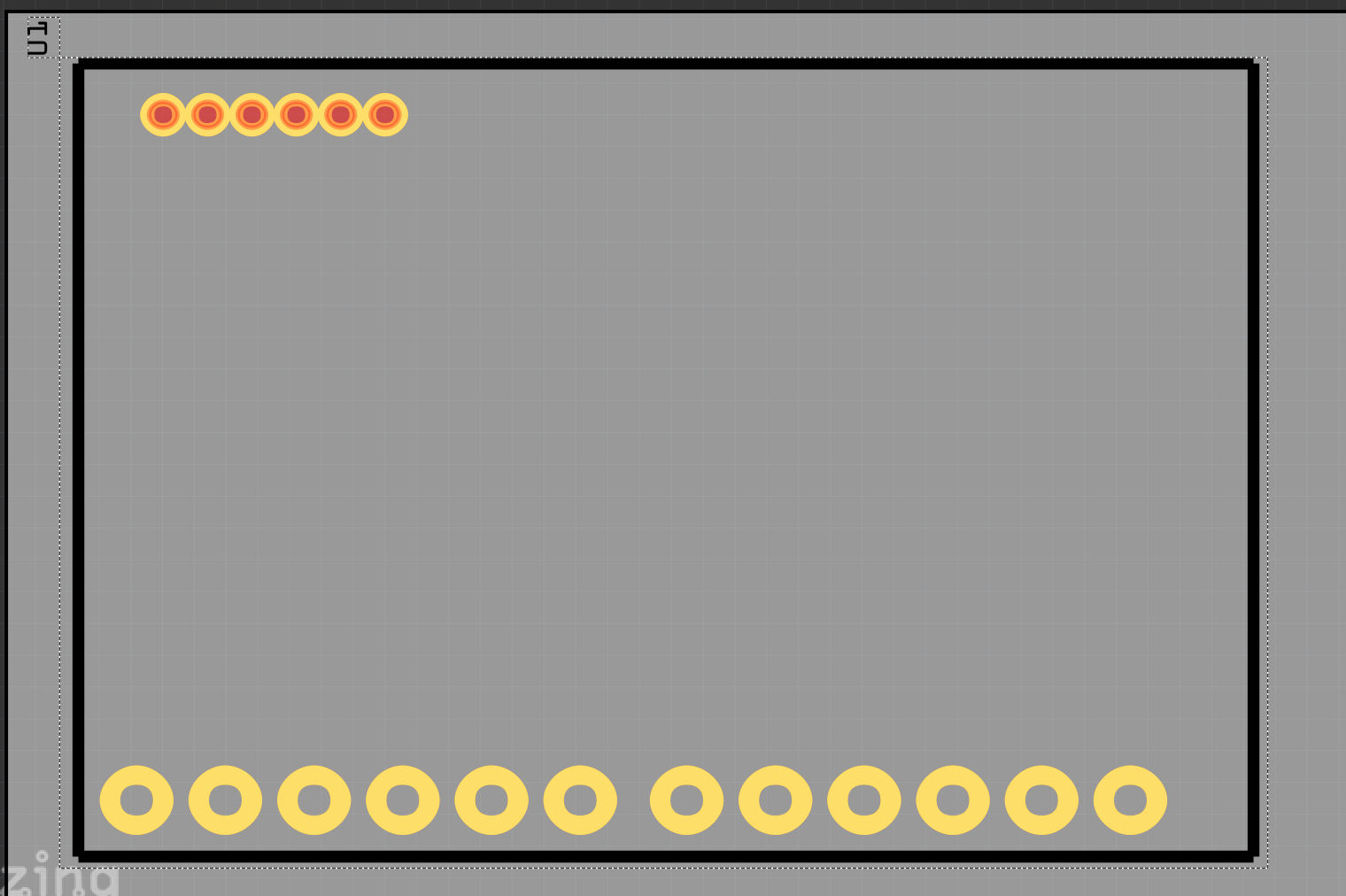
OK , I have replaced the part with a new one (you will need to delete the old one to load this one) with a partial pcb.
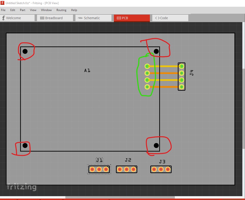
The 4 input pins appear in pcb along with the 4 mounting holes that are only on silkscreen (because you need to change the part to remove them.) The mounting holes will not be drilled by default. To drill the holes in your sketch you need to drag in a pcb hole part like this:
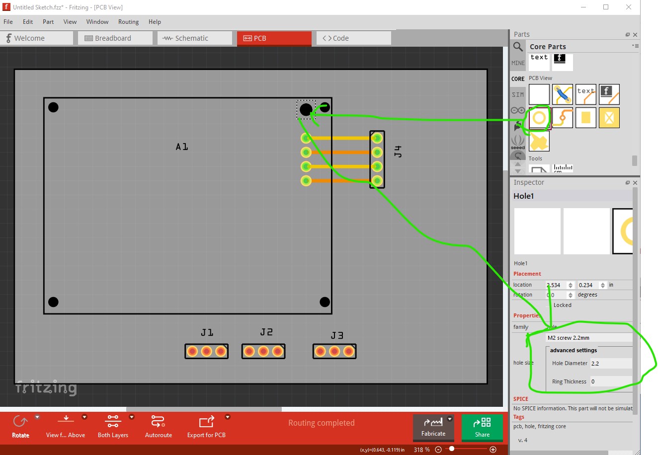
then set its size correctly in Inspector (the lower right window) and position it over the mounting hole in silkscreen, then do the same for the other 3 mounting holes. That will cause the mounting holes to be drilled in pcb (and if someone doesn’t want the mounting holes drilled, by default they won’t be.) I think this should do what you need. If not I can add more connections to pcb. You also need to check the positioning of the mounting holes against the real board as I am not sure the original part has them in the correct location. To do that print out the pcb footprint at 1:1 scale and compare it to a real board. Hope this helps! If not tell me what else you need and I can add it!
Peter
Thanks Peter so much ![]()