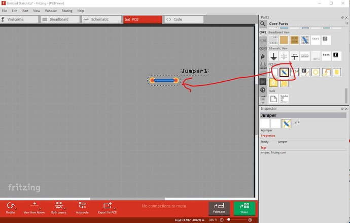
I just built my own CNC router. I found an Instructable which showed how to create your own PCB on a CNC router, which excited me since now I had a purpose for my new toy. The author suggested using Fritzing to design the PCB. Since I had built several breadboard projects using a 555 chip, I thought this would be a great first Fritzing project. I followed his instructions, but I could never come up with a single layer design which would work. The nature of the 555 chip has pin 2 going to 6 and the positive voltage coming into different sides of the chip. This creates crossed traces. Is there something simple I am not understanding about designing a layout.
On a slightly different note, every time i try to use “Autoroute” Fritzing crashes and exits. I am using a Beta version 0.9.3 on Linux Ubuntu.
Any help would be greatly appreciated.
Chris
