Which version are you using? Can you attach screenshots on what you did (including what you did in your illustrator app?)
Edit:
I have done this before
and you can use the SVG above to work. Highly likely your SVG has errors or the file is too big. I don’t have my computer now, so @vanepp can you help him?
I have version 1.0.5 and I can’t even open the part editor to begin adding anything on Mac (this may be my problem). I used Adobe Illustrator to create the SVG and just hit export with the basic settings.
It is a solenoid valve so presumably has electrical connections and requires a part. It is not clear from their data sheet where the connections are though (I would assume the two pins on the right and left but that is not clear from anything I see.)
Yes, the two pins on the right are positive and negative for the right side solenoid, and the two pins on the left are the positive and negative terminals for the left side solenoid.
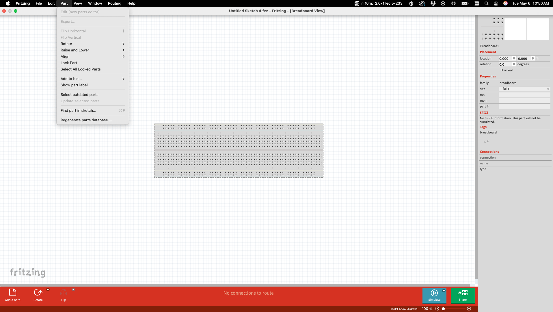
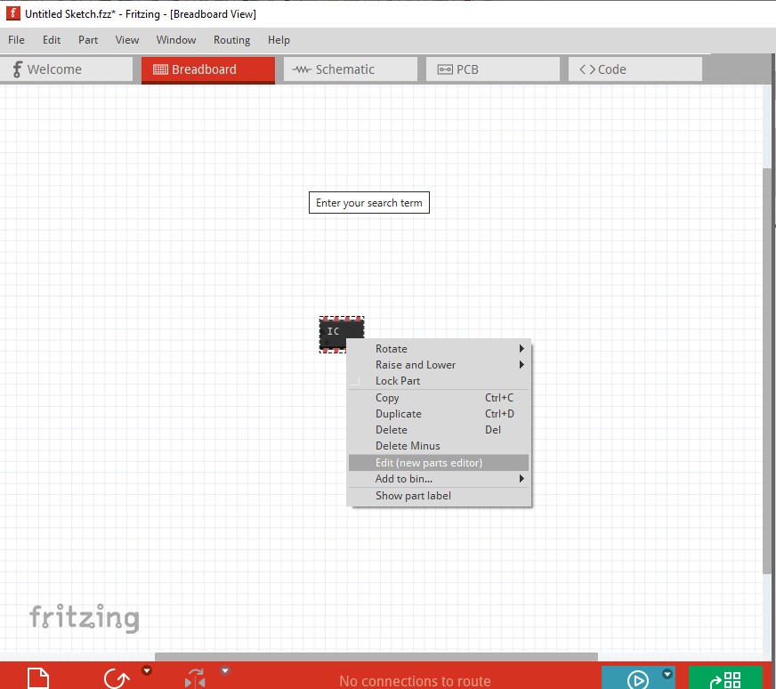
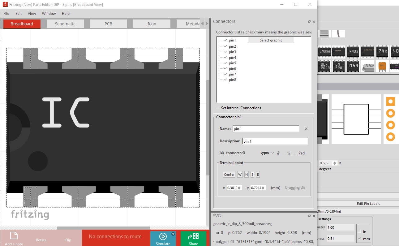
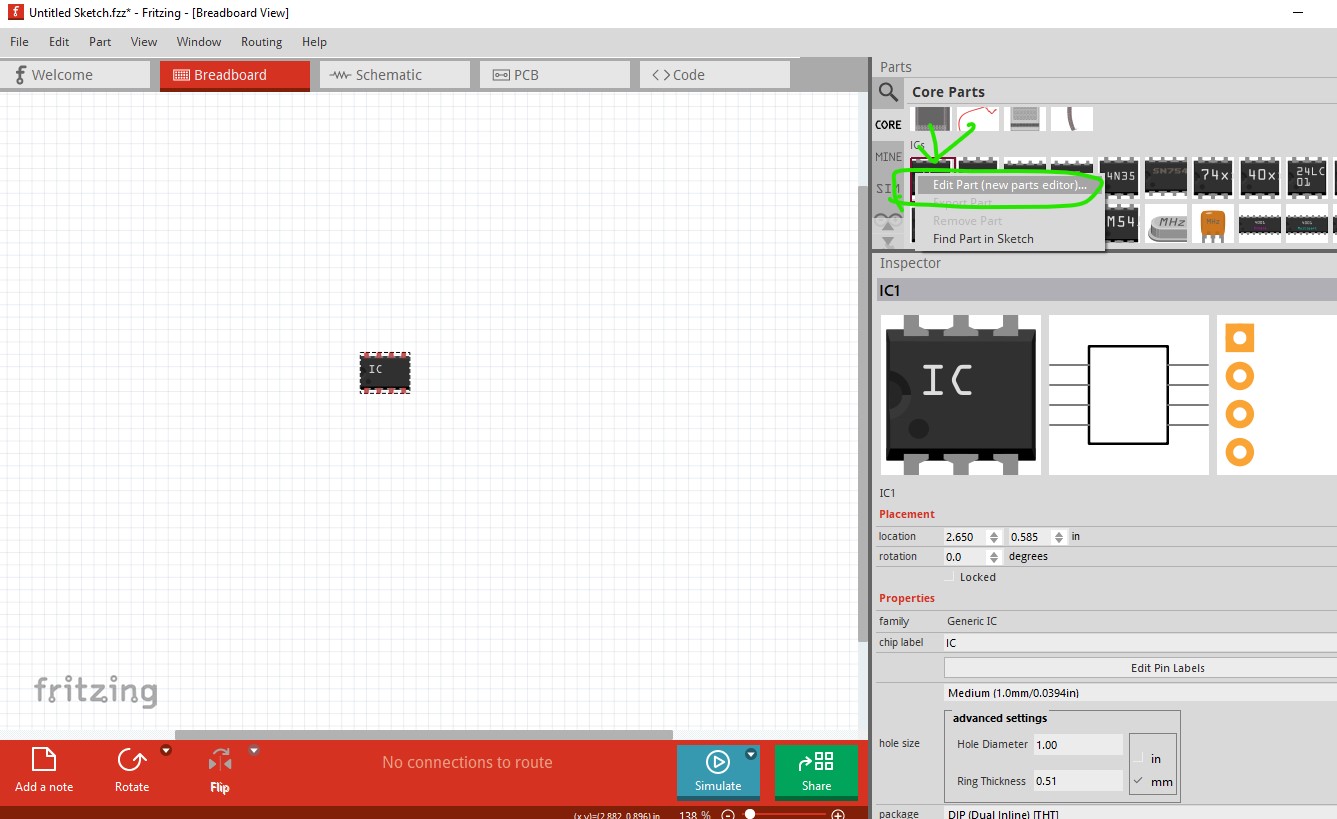
You can’t edit breadboards — start from an IC as a base (set no. of pins, pin labels then in the sketch, right-click and edit) Load imsge for view. Some have been documented in my part creation tutorial
This part should do what you want. Pcb view has been suppressed as not useful and the coil connections are generic (unless there are suppressor diodes in the valve the coil shouldn’t care about polarity, but impossible to tell for sure with so little information.)
I needed to edit your svg to remove the defs and insert them inline and change the dimensions from px, the Illustrator default, and in some versions the only choice which Fritzing may scale incorrectly and Inkscape which is what I use certainly will. Another parts maker that uses Illustrator (an older version that will only do px) imports the svg in to parts editor (which apparently deals with 72DPI Illustrator svgs) and that converts the svg to inches at the cost of an import to parts editor. Then in Inkscape I rescaled the svg to be the correct size according to the data sheet defined in inches. The defs in your svg may or may not work in Frizing (I didn’t try) Fritzing only supports the Tiny 1.2 (I think!) svg subset and not linear gradiants or other things (px in font size for CSS compliance for one off the top of my head.)