Hello, I’m new to Fritzing and this is the first part I’ve made. It’s a standard 4050 Hex buffer (CD4050, HEF4050, 74HC4050, etc) for a project of mine. I hope other people find it useful too.
Thanks for the help and advice from @vanepp and @microMerlin. I’ve tried to stick to the graphics standards, as I intend to use this as a template for the other parts I need to make.
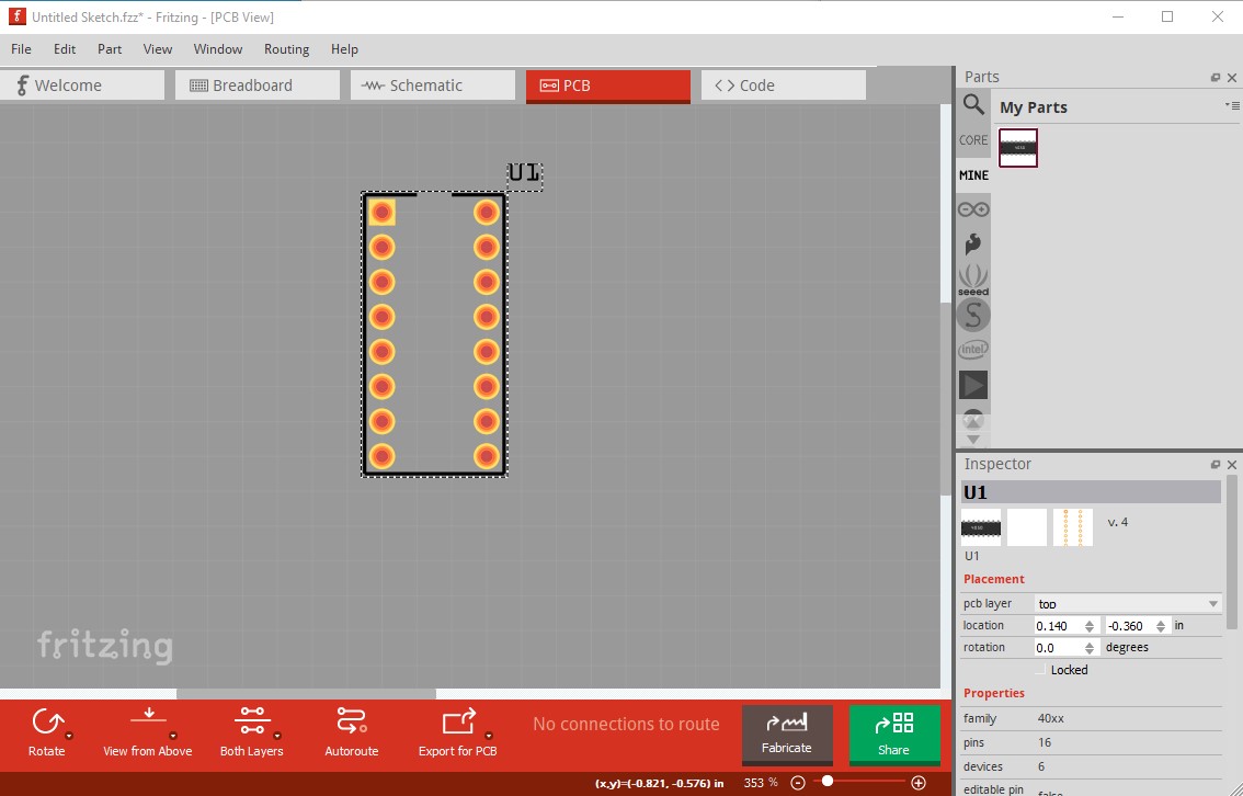
I’m impressed! Your first part, it uses schematic subparts, and is basically perfect. FritzingCheckPart’s only complaint is that the “dup” pin name is a duplicate and technically should be unique, because in some rare circumstances the pin names are used as an index. That doesn’t apply in this case so it is fine as is. FritzingCheckPart also complains about the lack of a pcb svg for it to check, but that is a FritzingCheckPart issue that I need to fix not your fault . Another annoying Fritizng quirk: here I dragged the part in to pcb so it is aligned vertically as desired:
note moving the top element didn’t effect the rest although I just discovered that you can drag a selection box around the entire part then move it and it will do them all at once!
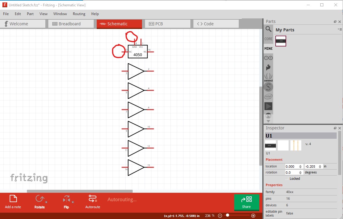
Is that the “NC” name for the “no connection” pins?
I noticed the quirk about placement alignment. Whichever view I insert to, it aligns to grid, but the other views are off. Also, if you place in schematic then the pcb alignment is rotated 90deg.
Yes. That said, as long as family and variant (and possibly all the rest of the properties) are different, which they usually are, the index doesn’t get down to the pin names and so shouldn’t be a problem. Many of the parts in core parts have duplicates in the name field (not that that makes them correct though )
This is similar to the alignment issue. Something is missing in the ipc call that creates the other 2 views and align to grid isn’t activated.
It actually appears to be random (probably whatever was last in that field.) If you do a place 10 times in schematic they will all be correct, but in breadboard and pcb you will get a selection of correct and rotated parts in no particular order. The code does an ipc to create the other 2 views and something in that call (although I could never figure out what was missing ) isn’t set to cause it to do both alignments in the other views, Hopefully someone smarter than me will be able to figure it out and fix it!
 . Another annoying Fritizng quirk: here I dragged the part in to pcb so it is aligned vertically as desired: