Thank you very much for your report @vanepp: I’ve updated the parts taking into account your changes/suggestions, although not all of them, as I consider some to be overcorrections:
- You removed my Icon view for the motor, which was different from the Breadboard view.
- The JST connector has a pitch of 2.50mm, not 2.54mm(0.1in) as per your corrections.
- The motor schematic symbol has been updated following your idea but respecting my own original drawing and accurate info (which coil lead connect to where, naming, etc.).
- In the driver schematic symbol I decided to keep the whole name to differentiate it from the ULN2003 IC: it’s a module, not a breakout board.
- Your SVGs contain metadata (Illustrator?).
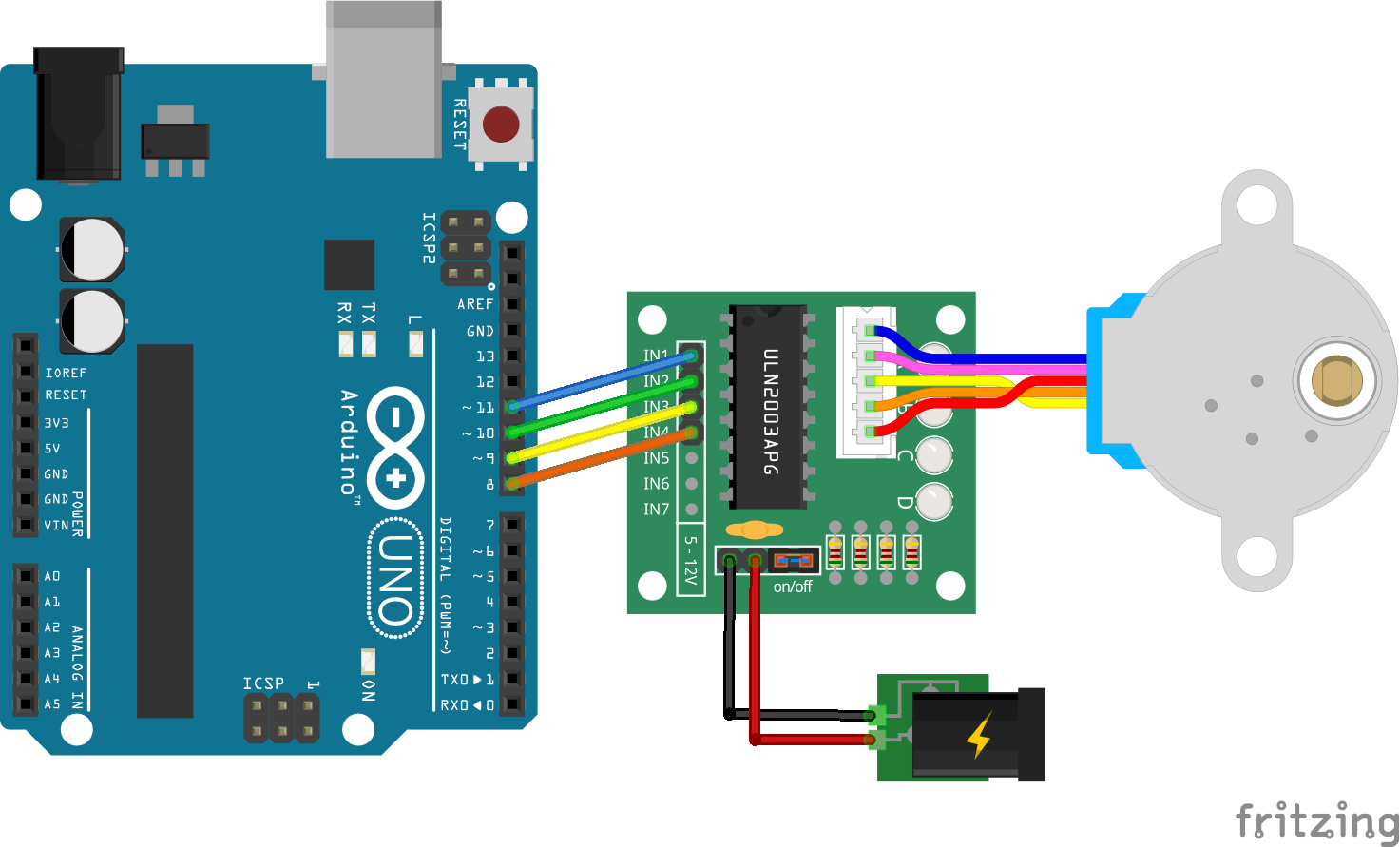
I also updated the fritzing file example: 28BYJ-48-driver_and_motor.fzz (36.8 KB)
Now, some aclarations:
My original part worked fine: it was NOT a problem of alignment (did you try the attached FZZ file?) but, as you mentioned, a question of pins genre. The spacing was not perfect (now it is as I sacrificed/traded accuracy for usability), but it appears that Fritzing assumes female pins to be in the bottom (because of the breadboard?) and male pins on top when you drag some part into another (to connect), so the weird effect result is that you had to connect the driver board to the motor, and not the other way around. It was unnatural so I swapped the pins genre in the JST-connectors for both the motor and the driver and it’s easier now (again, traded accuracy for usability).
I didn’t find this. What I saw instead is that you changed the JST connector pins from 2.50mm to 2.54mm(0.1in), that was not a problem anyway.
I won’t use Fritzing to create PCB’s (I use KiCAD) so I followed your recomendations there, although it doesn’t make any sense to me to use the PCB footprints for this two parts, especially the driver itself, as it is a module with THT components that won’t fit in a PCB (but I’m no expert in these matters ![]() )
)
Best regards!