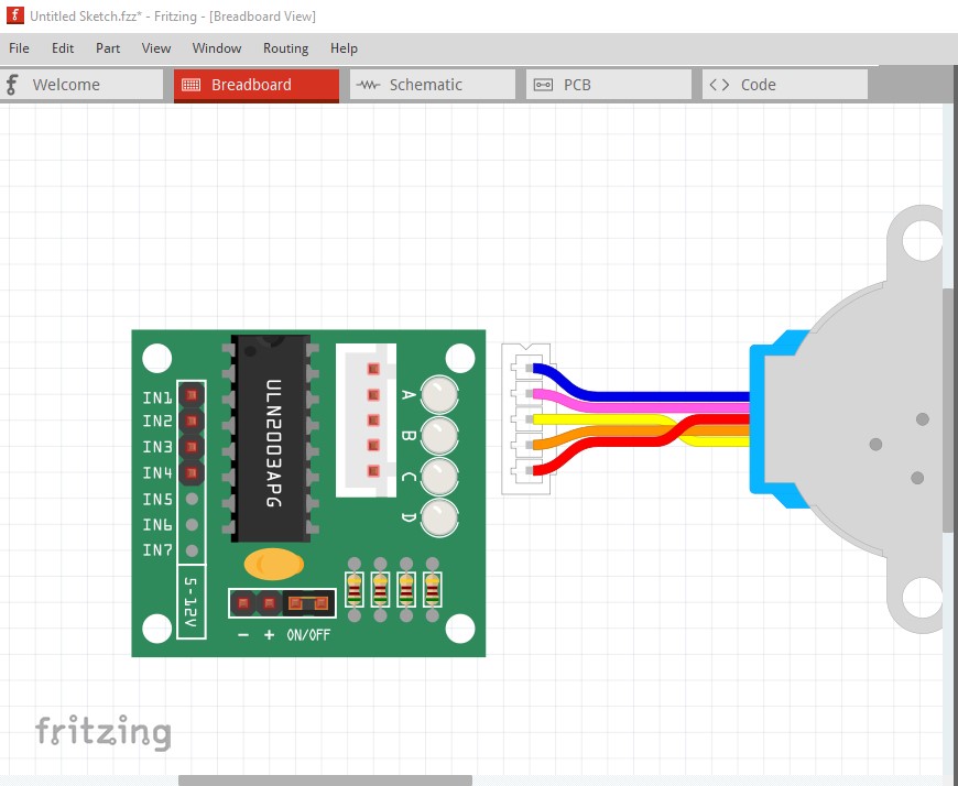
Nice job, although with a few issues. I assume because the stepper has female pins you were hoping to be able to connect the stepper to the module in breadboard and have it connect. Unfortunately the current breadboard doesn’t align on 0.1in boundaries so that doesn’t work. I moved the connectors in breadboard slightly so they all align and now that works:
then move the motor over the connector on the module

still no connection (the pin is red, not green) so you have to move the module left then back to get it to connect
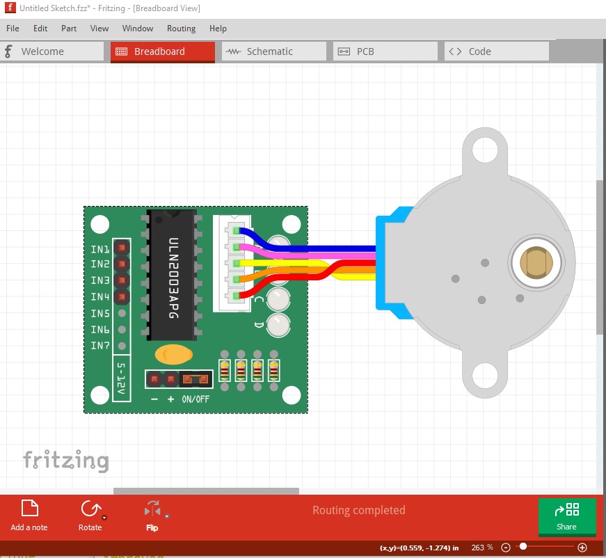
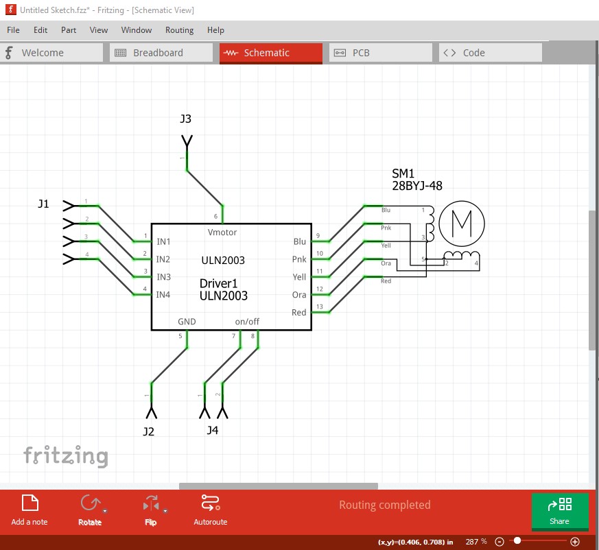
now we have a connection (green pins) and rats nest lines in schematic
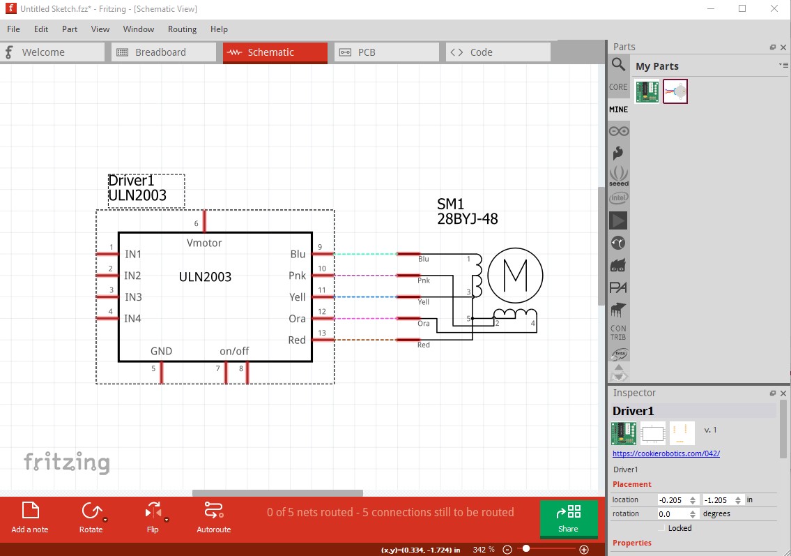
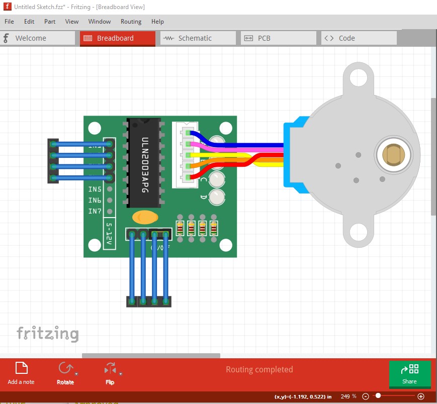
(you will also notice the motor schematic looks quite different to ccomodate this connection!) I also modified both the pcb svgs, in the module I removed the text as text can be added in the sketch (but the user has to change the part to remove text included in the part which is why text isn’t recommended in parts!) As well I moved the connectors to their real positions and added circles for the mounting holes in silkscreen (again if the user wants the mounting holes they can drag a hole part in to the sketch to produce them, if they are in the part the user has to change the part to remove them!) In the motor the holes were slightly to large so I set them to the standard 0.038in for header pins. Here is the complete test sequence of the two parts (including gerber output)
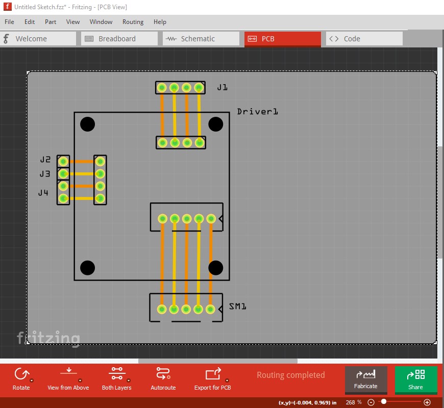
and the output gerber files for the sketch.

and finally the two modified parts
28BYJ-48 Driver Module-improved.fzpz (17.3 KB)
28BYJ-48 Stepper Motor-improved.fzpz (8.3 KB)
Peter