Initial part submission, removed part from post because it was revised to fix issues.
Looks pretty good. A couple of minor issues: you are missing the schematic layerId, the holes in pcb are a little large, and the re are px in the font size. The lack of a layerId means the part won’t export as a pdf or svg, the px in font size will set the font size to 0 (causeing the text to disappear) when the part is edited by the parts editor. The hole size in pcb is 0.039999 where for a .1 square pin it should be 0.038. The easy way to fix that is copy in a pad from a generic header (which is the correct size) and then copy the radius and style parameters of the pad in to you existing pads. Alternately the hole size in Inkscape is hole size = diameter of pad - (2 * stroke width), where the stroke width should be 20 thousandths of an inch. Given the odd scale of pcb it is probably easier to copy a correctly sized pad from a header.
Peter
Second part submission, removed part from post because it was revised to fix issues.
Better, but still a few problems (I’m using a development version of the parts checker here:
)
Warning 24: File
‘svg.schematic.prefix0000_a14846437c2c489714405ed9c979c207_1_schematic.svg.bak’
At line 58
Font family sans-serif is not Droid Sans or OCRA
This won’t render in Fritzing
Error 37: File
‘part.LCD2004-I2C_.fzp.bak’
This is a smd part as only the copper0 view is present but it is on the bottom layer, not the top.
If you wanted a smd part change copper0 to copper 1 at line 40
If you wanted a through hole part add the copper1 definition after line 40
Error 69: File
‘svg.breadboard.prefix0000_a14846437c2c489714405ed9c979c207_1_breadboard.svg.bak’
At line 19
Found a drawing element before a layerId (or no layerId)
Error 69: File
‘svg.schematic.prefix0000_a14846437c2c489714405ed9c979c207_1_schematic.svg.bak’
At line 16
Found a drawing element before a layerId (or no layerId)
The warning indicates that Fritzing will have substituted one of the supported fonts (OCRA or Droid SANS) and isn’t serious. The SMD part error is because the pcb svg needs a copper1 group that contains the copper0 group to be a through hole part (which is what you want here). The last two indicate there isn’t a group breadboard and schematic that contains the entire document. The only thing I know of that that breaks is svg and pdf export, the part won’t show up when exported, but otherwise works fine.
Peter
I do not know how to fix the Error 69 issues. Removed part from post because it was revised to fix issues.
Luckily this is really easy. Just open the svg, edit->select all (assuming you are using Inkscape) object–>group and name the resulting group either breadboard or schematic depending on which svg you are doing. The name needs to match what is in the fzp file but that is normally breadboard and schematic. If you are using an editor other than Inkscape, you just need to select the entire document then group it and change the group id.
Peter
1 Like
OK, thanks for the help! I have attached the latest version as there is only one informational message now:
This is a smd part as only the copper1 view is present.
If you wanted a through hole part add the copper0 definition before line 40
This is OK as I am only using the bottom of the LCM1602 backpack board to identify the connections to the LCD2004-I2C display module from the connecting device (Arduino). The other connections on the LCM1602 have no meaningful reference for this part.
LCD2004-I2C.fzpz (19.5 KB)
1 Like
While it will work like this, it is preferable that it be a through hole part (i.e. have a copper0 group under copper1) because in a two layer board the pads will be only on the top layer and thus difficult to solder. It is also usual to have a silkscreen layer that shows the outline of the part so you don’t try and mount components in the space the LCD will take.
Peter
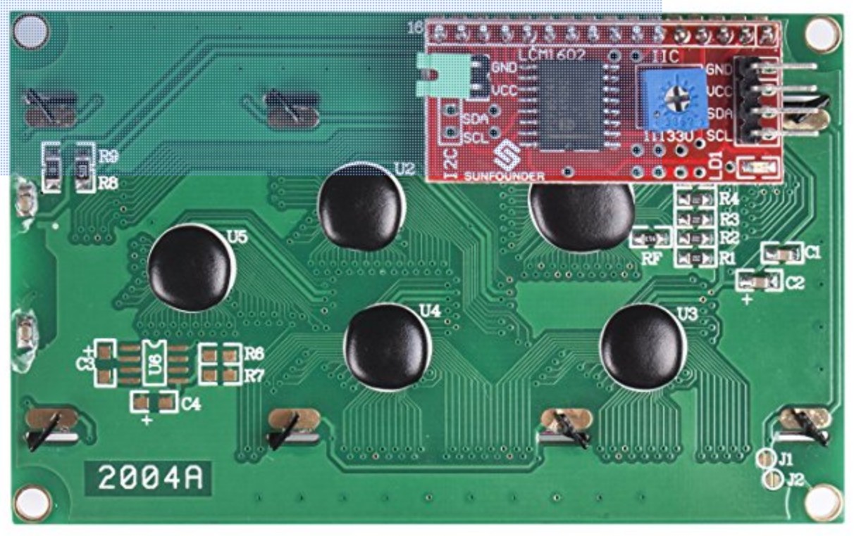
As per my previous post, the product has 2 PCB’s and not one. The LCD module is soldered directly to the LCM1602 using the headers on both PCB’s. Both are also individually available from vendors. When the parts are combined we end up with LCD2004-I2C. There are NO components to mount on the PCB, just a 4 pin right angle header.
Bottom line, the part works in Fritzing in a sketch and correctly shows the breadboard, schematic, and PCB connections. If more work is needed, I will leave it up to someone else in the community. I was trying to post a part that people have requested and that I needed. It works for my purposes as is, so I am done.
Thank you for all of your help in cleaning up the part!
Best regards,
Ken Harpster