This is my first PCB and first time using Fritzing. I am trying to create a simple Transistor array to drive a series of mini 5v solenoids using an Arduino Due. The final layout will have 2 of these boards for a total for 40 solenoids.
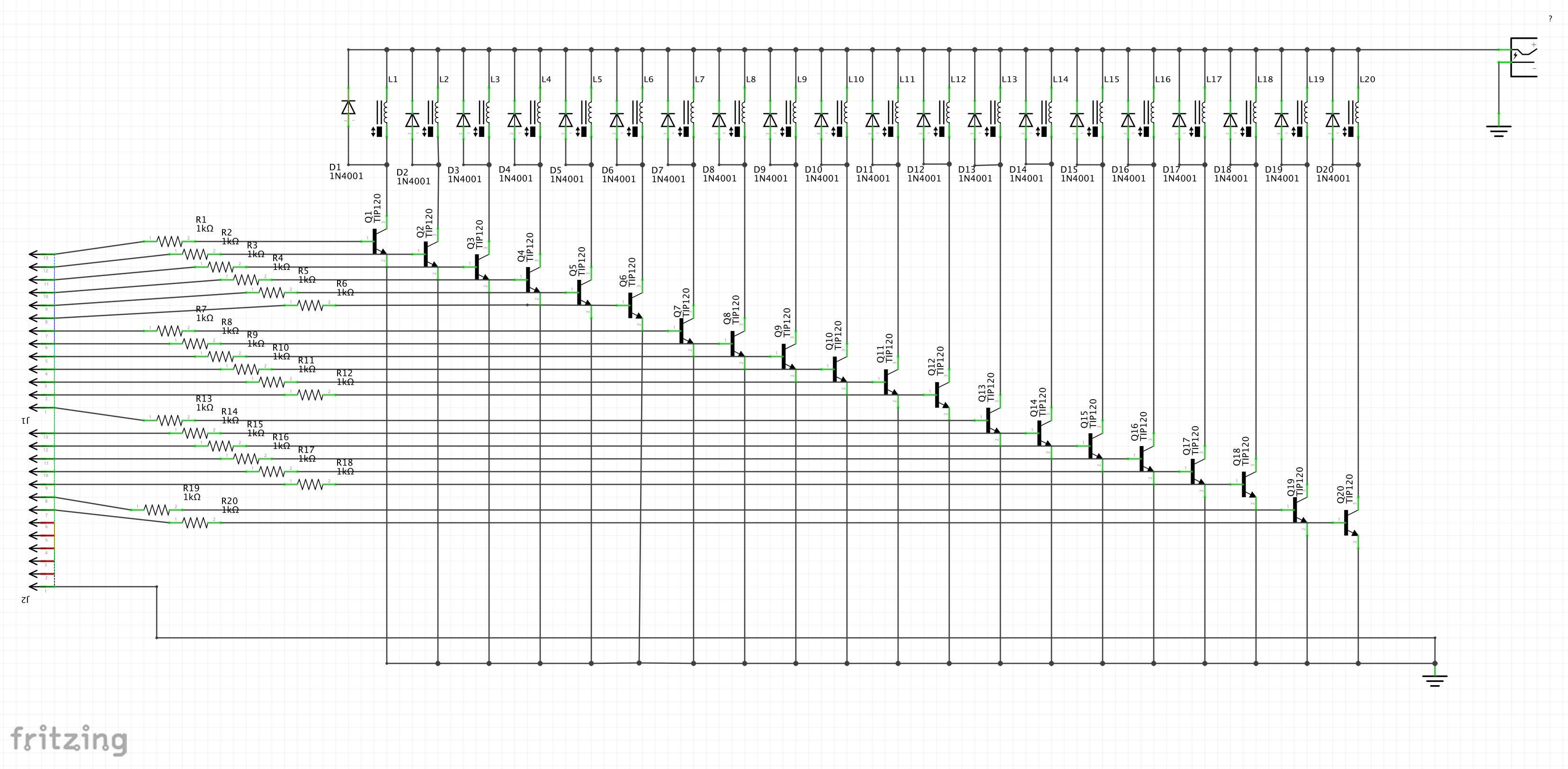
I have drawn the schematics first, but now that I am routing the PCB I am getting all sorts of weird connections, which makes me think the schematics is wrong. Could you please have a look and let me know if you can see anything odd?
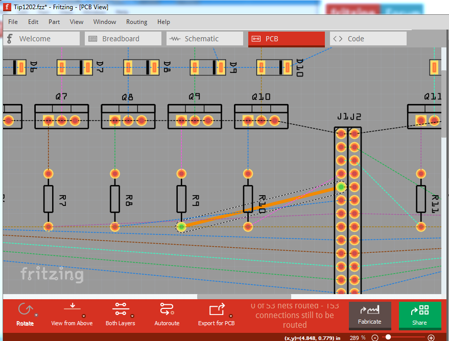
I don’t see any problem, what you are seeing is the rats nest lines formed by the connections in schematic. If you double click on a rats nest line it will create a trace. Once the trace exists you can click on it and drag it to where it needs to be to make the routing work. Here I have double clicked on one rats nest line in pcb to create a trace:
As it stands it is difficult to route the trace because Fritzing will select and create one of the other rats nest lines. So click View->Ratsnestlayer which deletes the rats nest lines from the view for the moment and then click on the trace and drag it to the correct position like this:
Of note here is the two end pads are green rather than red, which indicates you have the net properly connected (red would indicate the trace is not complete, which may happen if you click on an end point and drag the resulting trace to a new end point, clicking on the rats nest lines is a better bet.) Now click View->Ratsnestlayer to show the rats nest lines again and do the next connection. If you (as I often do) get two rats nest lines, you can right click on the trace and then Delete to delete the wire, or just drag it out of the way and route the original trace, then do the second one when the first is done. The thing to avoid is making changes in more than one view (i.e. schematic and pcb) because if you short two connections together that shouldn’t be connected you can corrupt the routing database unrecoverably and have to delete all the traces (sometimes in all views) and start the sketch again. Best practice is what you look to have done, finish one view (schematic in this case), then take a backup copy of it for safety in case you screw up, then move on to the other two views and click on rats nest lines as they are showing the correct connections (i.e. don’t route traces where you think they should go as you may create shorts as noted.) Once you have the board routed, you should export the gerber files (File->export-> for production->Extended gerber) and use a gerber viewer such as gerbv to verify the gerbers are correct (there are some Fritzing bugs which will look fine in Fritzing but generate invalid gerbers.) If you post the finished fzz file I’d be happy to look it over for you.
Thanks so much for your help Peter, and for taking the time to write all that!
As you described I was having some issues with the rats nest. I ended up deleting all the diodes and adding them again and now it’s all fine.
If you have a moment could you have a look at the final design (attached), before I send it off for prototyping? I hope the connections around the solenoids and diodes are correct… I am not sure the circuit was right in the first place.
I also read you should add capacitors to make the signal more robust, but I am not sure where they should go and which type. Any ideas? (I am planning to use mini 5v solenoids with a separate power supply).
The pcb looks fine as is, but improvements are possible, advisable and easy to make at this point. The first item to consider is how much current the solenoids draw because there are a lot of them. The catcher diodes look fine (you may want to upgrade to schottky diodes from the 1n4001s though, schottkys are faster and have a lower forward voltage.) The idea of the diodes is to supress the back emf when the coil disconnects. It will raise the voltage (in the opposite direction to the applied voltage) attempting to keep the current constant. The diodes provide a path to discharge that energy. I would add a high current schottky diode in series with the 5V supply to the coils with a 100uf bypass capacitor to ground after the diode. The capacitor provides initial inrush current local to the solenoids. The diode protects the logic which presumably shares the 5V power supply from voltage spikes from the coils (if the 5V line on the coils gets above 5v, the series diode will shut off and not allow it to drag the external 5V line above 5V.) Next you need to figure out what the hold current for the solenoids is as that affects both the drive needed for the transistors and the size of traces on the pcb. If it is only 100ma (which is likely to the low side) 20 solenoids take 2A which is getting a little high for .1 connectors (typically 3A max current), screw terminals may be a better bet. If the solenoids are 500ma each we are looking at 10A worst case (all solenoids on) and need to move to high current rules. I see I may be under estimating currents here, a Adafruit small 5v olenoid shows 1.1A draw at 5V, which puts you well in to high current rules. In this case the signal robustness only deals with ground (because the transistor drive is only referenced to ground) so some changes to the ground configuration are all that is needed. You want to have one of the ground pins dedicated to driver ground and be independent (at least on this board) of the solenoid grounds (the connection between the two grounds needs to be at the microprocessor. Because the transistors are darlington you have 1.4 volts of noise margin and thus not a lot to worry about, but a separate ground is still a good idea (the issue being voltage drop in a high current trace will erode your driver noise margin so you want a ground trace that doesn’t carry significant current so as to preserve noise margin.) The place to start is with the steady state current of an activated solenoid because that drives a lot of the rest of the calculations and considerations. Then I would consider powering the solenoids via screw terminals (which can take multiple amps unlike a .1 header) and separating the power and ground for each bank of 10 solenoids to reduce the current in any one trace (and use larger traces for the solenoid power and ground traces.) How much of that is needed depends on the current draw of the solenoids.
