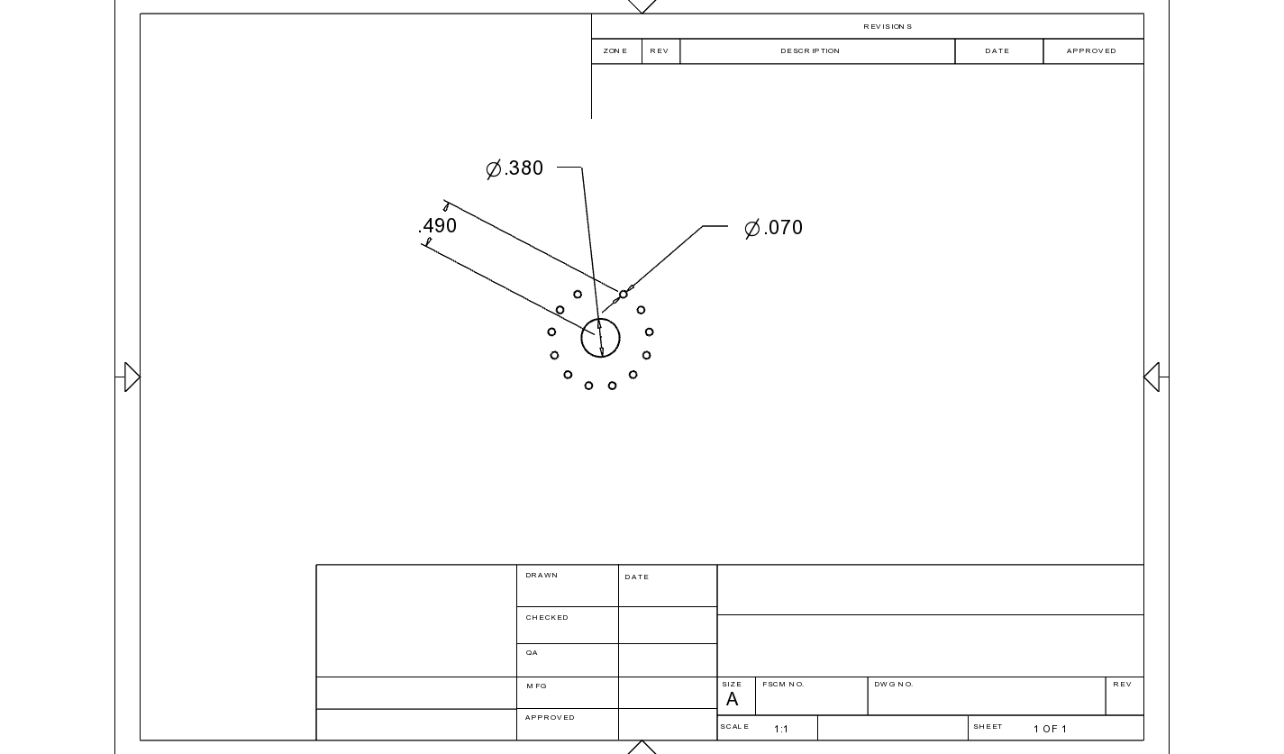
Working on new fritzing PCB layout for 100W 2ch tube amp. Using 12 pin- GZC12-Y. I’ve laid it out in CAD and attached dimensioned jpeg.
Be advised widely published 'net diagram of that model is incorrect (pin circle of 16mm) vs what I received (25mm). Latter is accurate- based on what I received & judging from pics of same products. Center .380"D circle ink only, please.
Peter has been great help… kindly ask for his assistance adding these models to fritzing library. If need cartesian points for hole locations, can supply.
Best,
oemcar
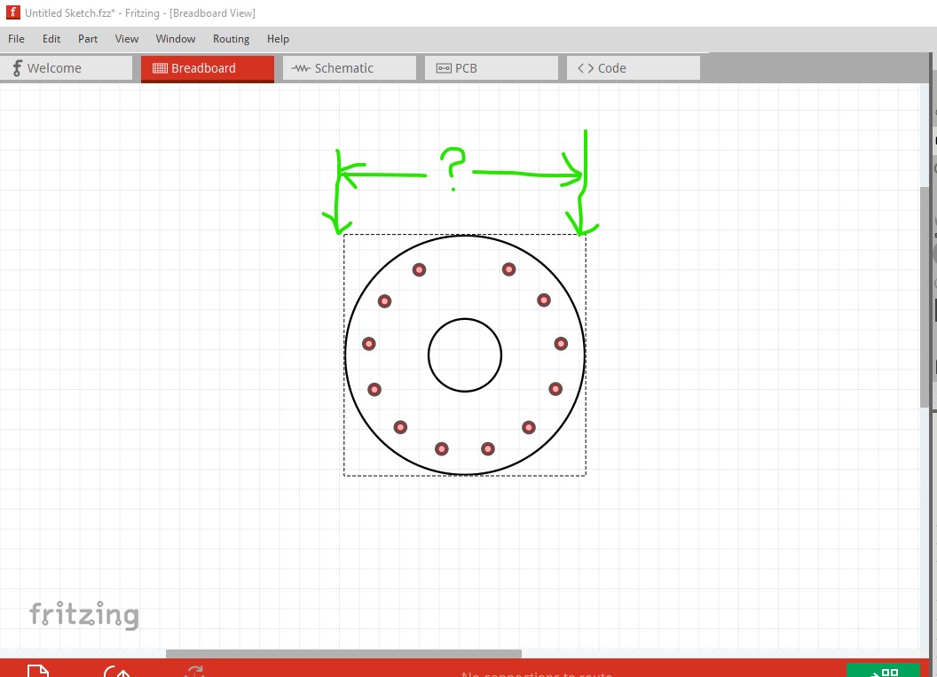
This should do almost what you want.
edit: replaced with a corrected version with 0.07in holes in pcb.
tube-socket-12pin.fzpz (5.5 KB)
The two issues in question are the size of the holes in pcb (currently set for 0.03in same as the 10 pin socket) and the diameter of the tube (which isn’t specified in your drawing.) I made it a bit bigger than the pins but I don’t know how much bigger it should be. The objective is to be able to put two tubes next to each other in pcb and have them not overlap.
Peter
Realized I forgot to attach the spec sheet late last nite Peter- lol.
The pin holes are .070". Thats same hole size as previous 7 & 9 pin sockets, iirc. Maybe youre thinking 10 pin version of 9 pin layout, which was discussed.
Thanks again ![]()
Jim
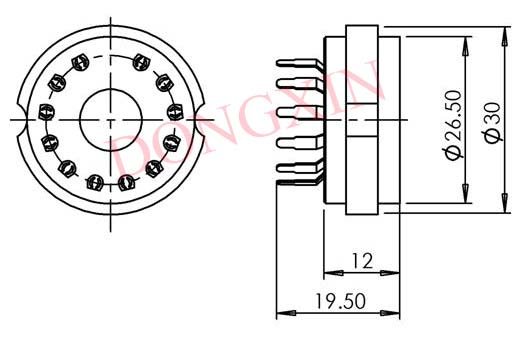
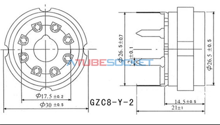
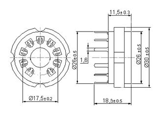
While were at it, here is the other popular socket (octal). Notice it uses notched inner hole for location, so ink’ed inner hole will need to show the notch for reference. Not shown on sheet, but inner hole is 8mm D. Also notice pin size is 2mm. Maybe 2.2 or 2.3mm D hole sizes??
Didn’t CAD this one cuz holes are easy 45* circular pattern. Looks like theyre on 26.5mm D.
Thanks Peter,
Jim
This should do what you want. Holes are 0.09in (around 2.4mm) it would be a good bet to print the footprint at 1:1 scale and compare it to a real socket to make sure it is right though. I assumed the pins are on a 17.5mm dia circle from the drawing above.
edit: Change pins to be on a 26.5mm diameter circle as requested
edit3
replace what i hope was the original part here which I updated by mistake!
tube-socket-Octal.fzpz (6.0 KB)
Peter
The actual tube pins are on 17.5mm D circle, but what we need for PCB layout are the socket pins, which are on 26.5mm D circle.
Thanks,
BTW- 12 pin socket layout is spot on ![]()
OK, I just replaced the octal part with one with the pins on 26.5mm dia circle. See if that does the job.
Peter
That works, Thanks Peter-
Library now contains the 4 most common tube socket types. Theres 1 more called magnoval thats used some, but I don’t have an actual part to check print, so we can visit that later if ok.
Best,
Jim
Peter,
Now have print to develop single 9 pin socket that can be used for 2 different tube app’s. Attached below. Shift angle of 36 degrees. Base circle D of 26.5mm. Socket pin hole D of 1.8mm (.070"). This base will allow Magnoval and Novar tube bases to be used in Fritzing layouts.
Thanks for all your help, Peter,
Best,
Jim
Try this one. I rescaled the current 9pin socket up a bit and set the hole size to 0.07in. It looks to fit on the rescaled jpg but a real part is the true test.
edit:
Update part with reduced pad diameter
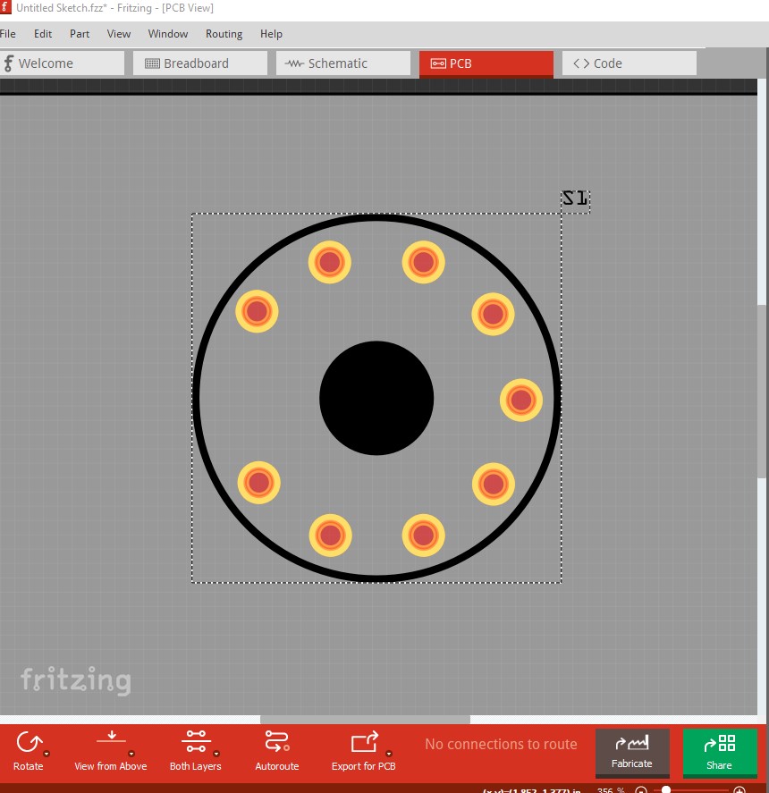
edit2: Remove the center black circle except in pcb where it is replaced with a circular outline where you need to drag a hole in the sketch if you want a hole at that position. (update the correct part this time!)
tube-socket-9pin-Magnoval-Novar.fzpz (4.1 KB)
now to correct the part above I screwed up!
Peter
Peter, here is what I measure on screen w/ print spec in parenthesis:
Outer circle- 33mm (30)
Inner circle pins- 24.5mm (26)
Pin diameter holes- .070" (.070) good here
Copper pad dia- .190" (.150)
No print spec on copper pad hole diameter, just going off other 9 pin diagram measurement. Not sure easiest way to modify, maybe start by scaling entire model up 5%. That should get our 26mm pin circle close enough. Offset or redraw outer circle to 30mm. Decrease solder pad to .150". I realize hole size will grow 5% by entire scale function, but still close enough, imo.
Thanks for your help,
Jim
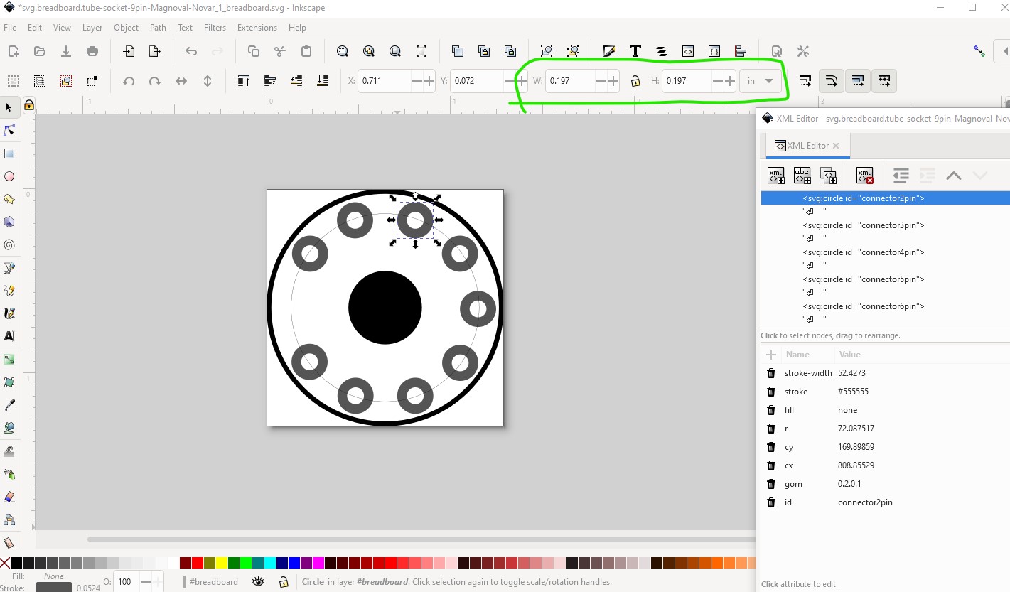
OK here are the current measurements (some are a little off because I had stroke-width scaling enabled by accident and didn’t notice til now!)
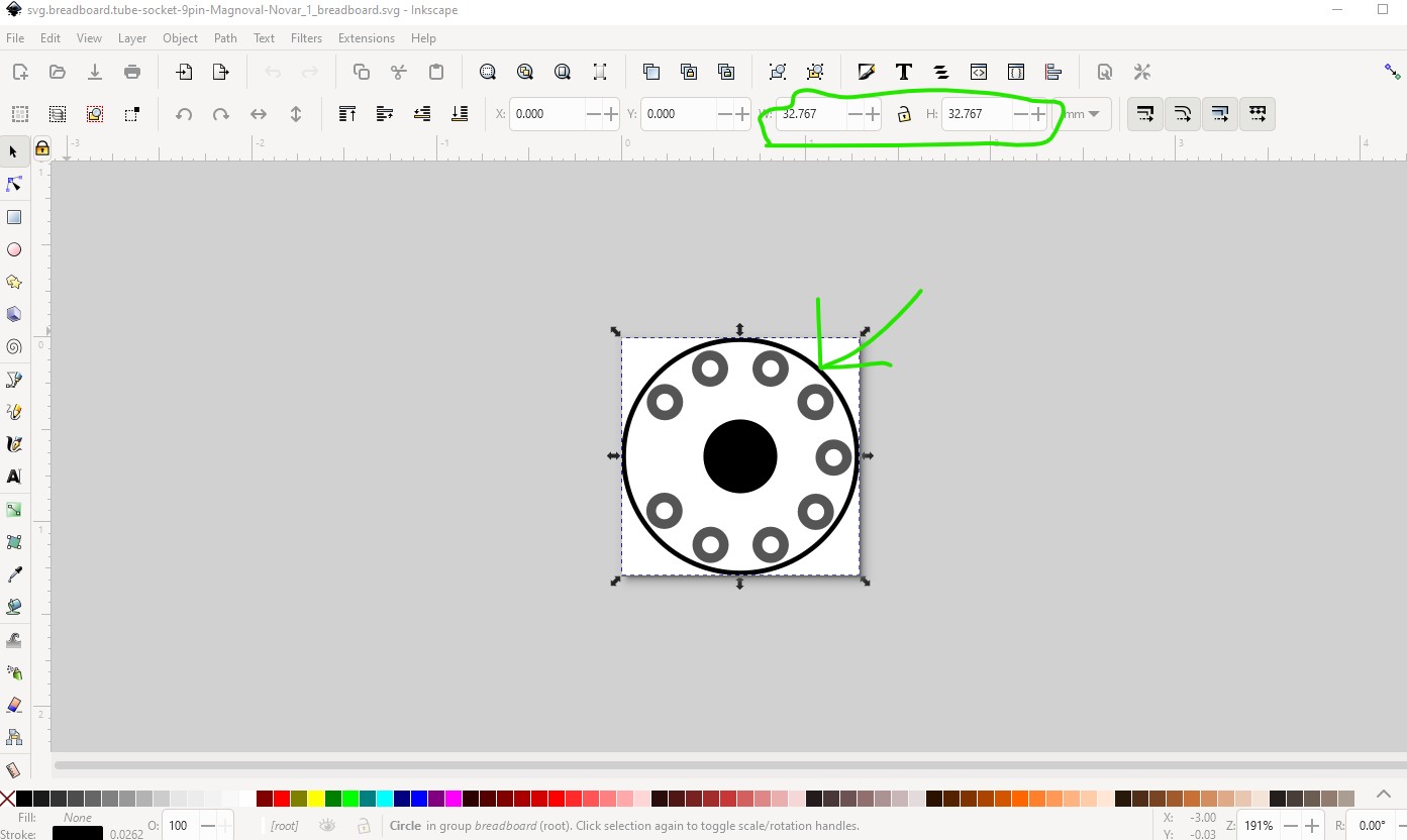
Outer circle diameter is 32.767mm
bottom of the pads is 20.6mm (is that the number that wants to be 24.5mm?)
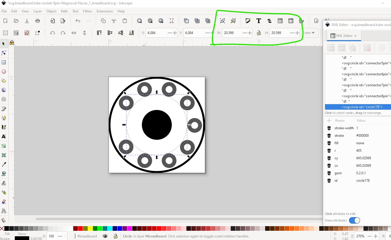
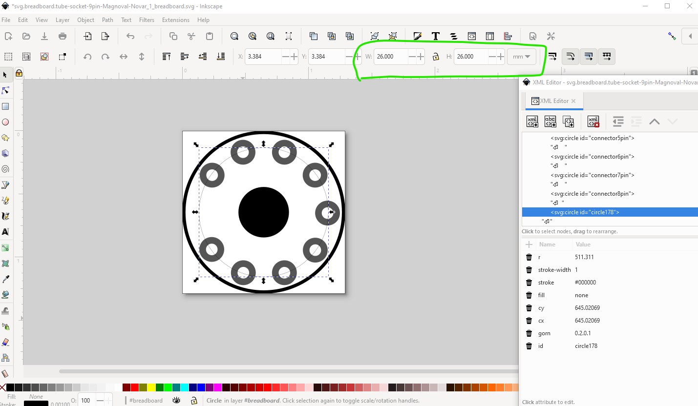
center of the pads (the important one!) is 26mm which is as specified in the data sheet. So are you saying this one needs to be 24.5mm rather than 26?
The pad diameter is currently 0.197in cutting that down is trivial. The most important number if going to be the one directly above for the center of the pins as that is where the holes will be drilled!
Peter
Peter,
The first #'s in last post are what I measured on Fritzing PCB screen with the cursor on your download. #'s in parentheses were what I was requesting. Method you are using to measure circular pattern is more precise than my ‘moving cursor’ method. If circular pattern of pin holes is currently 26.0mm thru the centers, then we are good. You are right, thats the most important measurement. If trim .047" off solder pads D, then think thats it
Thanks again, sir.
Best,
Jim
That does look a lot more reasonable. The ring is 40thou
I’ll replace the part above with the new one. Then printing the footprint out at 1:1 scale and checking it against a real socket would be a good bet.
Peter
Indeed,
Worked last 2 months to secure 100 pcs of this design- then more if needed. This was challenge across language barriers- but successful. Will print out this rev and check plot to socket match.
Thanks Peter
Jim
Peter,
Revamped design looks great dimensionally. If I could ask for one more ticky-tac change- could you please show the center circle as hollow, instead of filled? This change allows fritzing users easier trace visuals when designing in that area- as in latest design attached.

Thanks in advance,
Jim
Without Peter’s continuous contributions, I believe fritzing could not be viable…
He is the ‘conduit’ thru which most happens- I am most grateful,
Jim
Did I not upload the corrected socket? I did it, but I don’t see it here. In case I indeed never uploaded it, here is a copy with the center circle as a ring instead of filled.
tube-socket-12pin.fzpz (5.5 KB)
Peter
Peter,
It was there, I loaded it & all good,
Thx