Hi all …
I’m totally new in this field and its just a hobby for me , to excuse my mistakes
i’m working on simple project … and i use one digit 0.8" seven segment ( 4 pcs ) and i want to make a PCB but i cant find this size in core or external library …
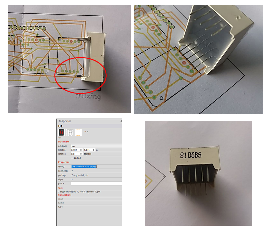
i used (u1) part which i found in core library
but when i print it to test it on a paper i found a difference on pin distribute vertically …
“U1” does not say much about the part you used. All it tells us, is that the part has the label field defined as “U”, which is not unique. Many parts have a label of “U”.
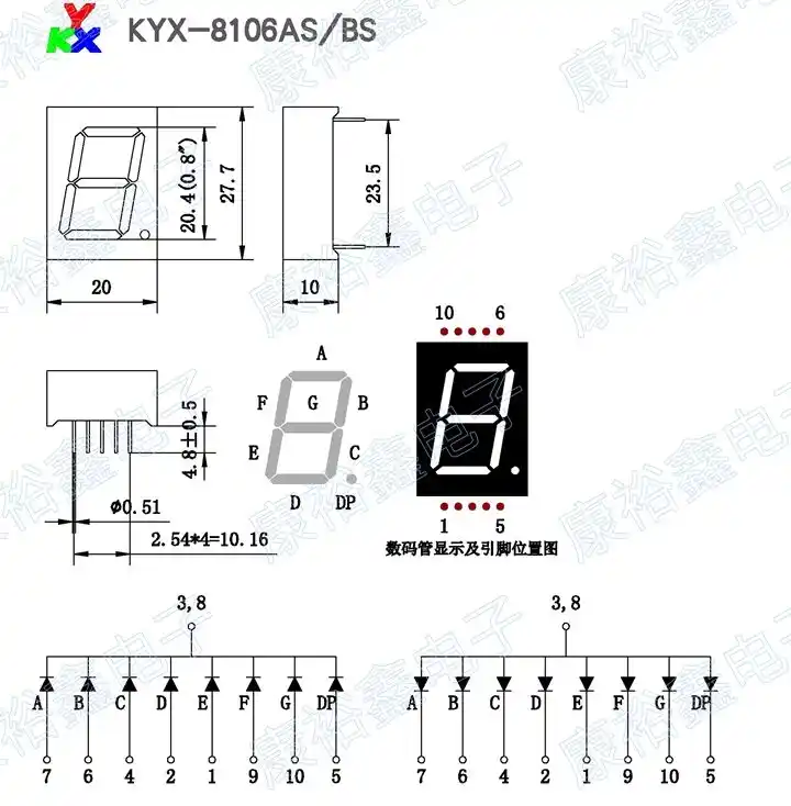
The screenshot of the Inspector window though, shows the family as “sparkfun charakter display”. The miss-spelling of ‘character’ in that is unique in the core parts, so you used the “7-SEGMENT-DISPLAY-1_-RED” part. That part is for displays that have a footprint with 0.8" (20.32 mm) between the pin rows. From what is shown of the datasheet, your part has 23.5 mm (0.925") between the rows.
You said your digit is 0.8". I assume you meant the distance from the bottom segment to the top segment (as shown on the datasheet). What is important to fritzing, is the spacing (horizontal and vertical) between the pins. The way (several of) the other core part displays are tagged, this has a size of 27.7mm (bottom to top of the physical block).
I do not see any 7 segment displays in the core parts with 23.5mm row spacing or 27.7 size. This will need a custom part. Which “should” be easy, but I also see that the existing parts have poor schematic representations. pins not 0.1" long, not aligned to the grid, bigger than needed. So that should be fixed as well.
You are my Saving Angel … yes it is … perfectly fit… you save me a lot of time and work (and i don’t know how to do it from first place ) thank you alot my dear friend Peter
Once you learn how to make parts, they are fairly easy to make. There is however a steep learning curve to learn how. Thus it is often easier for one of us who knows how to make parts to make one …