I made some PCB designs but noticed that I have to change hole sizes a bit. Is it possible to update the svg drawing file without resetting all connections?
At the moment I always lose all connections+traces. Any ideas?
I made some PCB designs but noticed that I have to change hole sizes a bit. Is it possible to update the svg drawing file without resetting all connections?
At the moment I always lose all connections+traces. Any ideas?
Hole size in what? A custom part in the sketch or pads you have added to the sketch or core parts? It may well be easiest to upload the sketch .fzz file that you want to change (7th icon from the left in the reply tool bar) along with what you want to change and one of us will have a look. If it is a part the “delete minus” option will delete the part but not the routing (you have to move the traces to remake the connections on the replacement though).
Peter
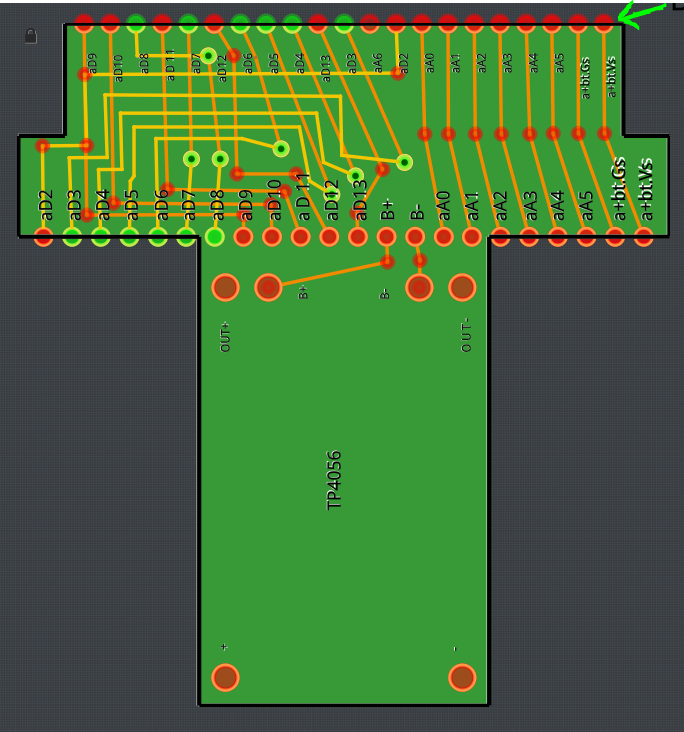
It’s a custom part I made.
I have all the holes/pads added inside the SVG file already.
Here a screenshot.
In this example I want to have castellated holes (I am afraid it might be an issue when I try to order the PCB later on). The ones on the bottom side seem to be fine, but at the top it somehow only shows half of it. (Same in the gerber file) I think the artwork border cut it off there.
The problem is if I update the svg file now it will remove all the hole links+traces. I have around 10 more drawings with a similar problem. Which would take me hours to replicate.
The best would be if it can keep all the hole links+traces while updating the drawing. Is that possible?
Yes the gerber will truncate at the board border line. There are two ways you can go (one more legal than the other  ). As noted in the first message you can select the part do delete minus and it will delete the part but leave the routing in place and you can add the corrected part back in them move the traces to remake the connections. That would be the official and safe way to proceed. The alternative (although make sure you export the fzz file first so you have a backup in case of problems) is to substitute the svg file in the mine parts bin. On windows that would be in
c:\Users\user_name\My Documents\fritzing\parts\svg\user\pcb
in a file like
prefix0000_62f0b0040f94a2199f992e77ef49734a_1_pcb.svg
in theory replacing that file should update the svg without doing anything to the routing (and as long as none of the pads have been moved). As noted the delete minus is the safe and approved way to do this. The gerber output code has some issues with pads that are being truncated though (it sometimes screws them up) so I’m not sure you can achieve what you are aiming for with Fritzing. Some of our better pcb folks (which isn’t me ) may have better suggestions.
Peter
Thanks for the advice!
The delete minus function kind of worked.
Only problem is that I need to declare each pad again in the part viewer.
A bit annoying if there are 50+ pads to link.
The second suggestion you had with the file replacement somehow did not work. It messed up the wiring/connections somehow.