Hi everyone, I recently made a breadboard power supply which I called Toaster.
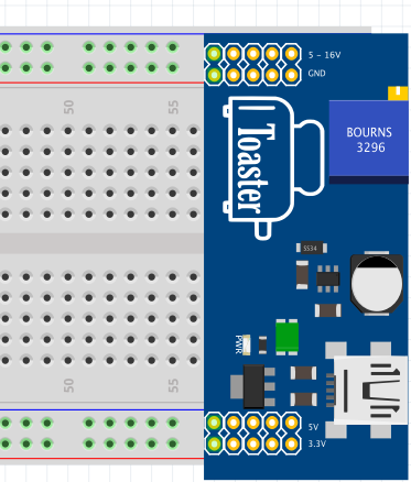
It is powered by a standard 5V USB port / charger and provides three outputs: 3.3V, 5V and variable 5V - 16V. It fits in nicely between the standard fritzing dual power supply rail breadboard.
Further details can be found here:
http://www.bradsprojects.com/toaster-the-dual-rail-step-up-breadboard-power-supply/
The fritzing part can be downloaded here:
Toaster Breadboard Power Supply.fzpz (28.4 KB)
Nice breadboard drawing - your trim looks better than the one I made.
I’ve never seen one with black dots in the connectors.
The gerbers don’t have holes in the PCB.
In the PCB view you might want to delete the black ellipses.
Then select no fill for the copper connectors.
The connectors also don’t seam to be round 1.552mm x 1.481mm
For some reason the gold doesn’t show in Inkscape.
In Inkscape the silkscreen is white…
If you need a hand I can do it.
I really appreciate the feedback Old_Grey although I can’t take the credit for the actual fritzing breadboard view since I had someone do it for me. I would certainly enjoy coming up to speed on it myself however due to other commitments at the moment I haven’t had the time.
I would certainly appreciate the help with polishing it off (as per your recommendations). I’d be happy to send you a free Toaster in return for your help.
No worries I will touch up the PCB - I nearly did it already just looking at the svg -.
No need to send anything out as it gives me something to do.
EDIT
One question, are the pins supposed to be on the std 0.100" 2.54mm pitch, because the outside rows are 19.5 std pins apart. And if you want to change it do you want 19 pins or 20.
Hey Brad,
Dee here. Good to see you’ve submitted the part here. I see you’ve already got a real feedback and Old_Grey has come forward to do the changes.
Hi Old_Grey,
Its me done the part on brads request. Yes, the pins are 0.1" (2.54mm) and has to be 20 all. I’m sorry I messed up at the end by using both illustrator CC and Inkscape along with latest fritzing update which for some reasons its now popping up errors on copper layers. Also I shouldn’t have used both for editing coz its kind of having mixup xml formats.
Anyway we appreciate and thank you very much for giving us a hand.
Regards,
Dee
Hopefully this one is right.
V1.1 Toaster Breadboard Power Supply.fzpz (44.7 KB)
I fixed the PCB dimensions - PCB has to be accurate for production reasons - and it measures ok, and gerbers and drill holes look correct.
The Breadboard should also be on a 0.100" spacing to connect with boards, so I had to scale BB view up for correct alignment. I had to go with 21 pins for BB for correct spacing, but the 21 in BB view doesn’t effect the mandatory correct dimensions required for PCB production.
Hey Old_Grey,
Thank you very much. But I’ve earlier done the modifications on the PCB and sent to brad and was waiting him to update the file here. But anyway he seems like busy today.
To be honest I appreciate you for being more precise but generally Breadboard View doesn’t effect much as long as the pins are connected. As I did expect that 21 pins might be needed for correct spacing.
Overall we’ll stick with your file for now considering it to be a craftsmanship work.
Thanks again.
Hi Dee and Old_Grey, sorry for the delayed response but it has been one busy day! In fact, it is 12:24AM and i’ve just found some time to sit down and reply here now.
I have just now tested out both your latest revision Dee that you sent through and also yours Old_Grey. Thanks very much to both of you. I guess I should upload Dee’s latest revision here:
Toaster_v01_Bread_Board_Dual_Supply.fzpz (32.2 KB)
As for yours Old_Grey, I tested it out and it seems the power supply rails are about 100mil out on the bottom. How did you get it to fit correctly? Making parts for fritzing seems like a very awkward process as I am now finding out!
Thanks to you both for your help.
Fritzing has a difficult part making process, because you have to make 3 drawings, but that’s what you pay for with the convenience of 3 simultaneous linked views, ie pain at the start but convenience latter. KiCad is a pain because it’s separate programs in one wrapper that aren’t connected.
Whenever you do a drawing or modify a drawing always add a 0.100" grid with snap to centre and you can’t go wrong. For Inkscape File/Document Properties/Grid.
I put a 20 pin header on the PCB drawing and it’s 20 pins outside to outside. The old Breadboard svg connected, but when I zoomed in on the connectors the right-hand ones were centre locked and the left ones were West locked - you can see it in your top pic -, so to make it neat I made it 21 pins so the vertical pins line up. Is the part supposed to mate with a 20 pin part in Breadboard.
I’m sure you guys will sort it out now you know about the 0.100" grid.
Fantastic, thank you for the tips Old_Grey.
The pins are supposed to line up with the top and bottom power supply rails. This then gives you a 5-16V variable connection on the top rail. GND on the rail just beneath it. Then the very bottom rail is 3.3V while the rail just above that is 5V. They all use the common ground rail.
Sorry for bumping an old thread but I was hoping to get in touch with Old_Grey for some help with a new project. I have tried to send through a private message but it doesn’t seem that there is an option for that - is there anyway that you can contact me?