I’ve noticed that, when it comes to wearables, there’s no simple way to include a display, such as one might wear on the wrist. (At least, I haven’t found any.) So I figured the next best thing would to to try to design one of my own.
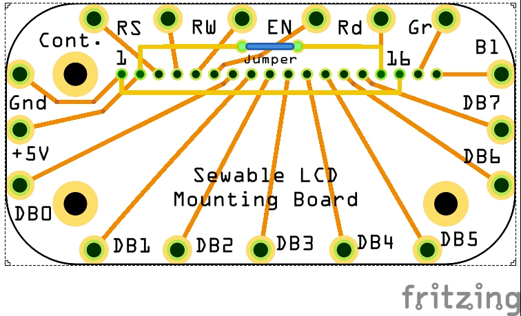
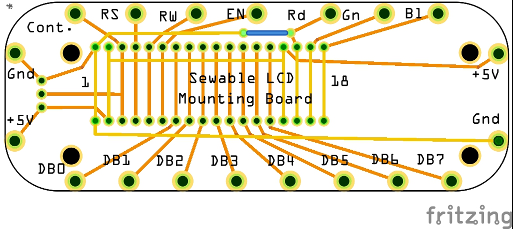
The character LCDs I like are the ones sold by Adafruit; this one in particular has my attention. The diagram below shows my (hopefully) sewable PCB design.
All it’s meant to do is break out all of the pins in a way that it can work with either 16- or 18-pin LCDs. The mounting hole in the upper right corner is meant to align with the one on the displays; the two lower ones should contain just plugs, to give the display board a little extra backing.
And I’d like to get some feedback before I go and spend money on a test board (or post the Fritzing files for someone else to do that).
My questions:
Is there anything wrong with the wiring? Is there a connection I’ve missed, or that I’ve made that shouldn’t be there?
Are the labels correct and clear enough? (Assuming the person is using Adafruit’s tutorial.)
Should I increase the board’s size to match up all the mounting holes on the display board?
Does this look appropriately sewable?
I’d like to hear from anyone who has experience in these areas, especially the last two.
First I’d suggest uploading your sketch file (the .fzz file) so we have the complete part to load and look at. While I don’t know anything about what special needs sewable has, I have a couple of concerns. You probably want a trim pot on the board for the contrast control even if the user does something else for contrast control, they have the option of having an on board solution. I was going to suggest series resistors for the LEDS but see they are built in. I think your wiring is wrong in that the Rd pad should go to pin 16 and the ground connection to pin 16 should be removed (as it stands the red backlight will always be on at full power and the Rd pin will be at 5V which is a bad thing to drive with a microprocessor pin.). There looks to have been a change in mounting hole sizes in 2016 as well (hopefully not position, just size). Access to the .fzpz file would also let me tell you if you will get holes drilled or not (to get a hole, the hole needs to be in the copper layers and correctly configured.)
The connection between pin 16 (which is where that one should be; as it is I have it on 15, so I’ll need to fix that) and the ground is for the non-RGB versions of the display, where that pin is used for power to the character display (and 17 and 18 not at all). When using with an RGB version, the jumper would be removed.
I’ve actually been going back and forth on including a place for the contrast pot on this board. As it is, the attached display will cover up everything but the jumper. If I expand the board to entirely back the display, then putting a place for the pot below the screen could be practical, though if the user doesn’t use that – for example, using an analog output instead – then it becomes wasted space. Since this would typically be worn on the wrist, space may be at a premium. (I suppose I could put a narrow area to the left with connections; that might work.)
It may be worth mentioning that the final version of this will probably use right-angle headers to minimize the profile (again, relevant to it being worn on the wrist).
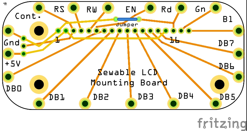
My mistake, I’m used to parts. This will be hard to turn in to a part (not impossible, but tricky because of the traces.) so the .fzz is fine (I edited the original post but obviously after you had seen it.). I’ll post an updated fzz in a bit with my suggested changes. I think you need another jumper to make this work with the rgb display, as it stands red is connected wrong for the rgb part.
Edit: I just realized this board isn’t wide enough to mount the rgb display. The data sheet says that display is 80mm wide and the board is only 70, so the mounting holes won’t fit. So here is my suggested mods (and why) so far:
I added another jumper and changed the trace on the RD pin so it will accommodate both your current and the rgb display (although the rgb is too long to fit the current board.) I changed all the pads to be 0.038 dia and 20 thou pad (this is the standard pad size for .1 header connectors which the LCD will be. For the external connectors on the edge, you may want to reduce the diameter to 0.030in as you will probably be using small gauge wire (24 to 28 ga) which need smaller holes. If you want to wrist mount this, I would probably use a suitable size header like this (placed but not routed) so all the wires come out one side of the board to run up the arm. You also probably want some more mounting holes on the left and right sides of the board to fasten the wrist strap to (the current mounting holes will have screws for the lcd in them.) You may want to do both for maximum flexibility (although routing may get a bit complex.) You also might want to put holes (no copper) around the edge of the board to give anchor points for thread if someone wanted to sew it on a shirt or such like (I did a couple of example holes on the two bottom corners here along with the unrouted header.) A late thought, a surface mount fmc connector which will take fmc ribbon cable may be a good (if hard to hand solder!) connection alternative. The fmc cables are very thin and fine pitch so may be more suitable than wire. Maybe just pads if someone wants to use them. That is my though on the contrast pot too, better to have the pads (which cost nothing but board space) and not use them to want one but not have the pads to connect it to.
Edit: I only just noticed your most recent reply above. The variable sizes between the 16 and 18 pin displays is part of why I only put a mounting hole on the upper left corner, relying on the headers at the top and the two “bumper” slots at the bottom for stability. Still, making the lower left one match up with the corresponding one on the board is probably a good idea. I’ll take a look at what you’ve done and see what I can incorporate as far as that.
The connections around the edge are what will be needed for conductive thread.
Thank you for the catch on the 0.038"/.02" size of the header connectors. I changed them all to that.
The sew hole size is about equal to what I can see on LilyPad, Flora, etc. I’m still trying to figure out (since I’m brand-new to Fritzing) how to expand the edgeward side of those pads to what I see on those boards.
I did widen the board so the post at the lower right could lend support the display. The displays that Adafruit sells vary in size depending on number of lines and characters per line, but this post (and its mate to the left) should give the kind of support that keeps the board from pushing down. Only the upper right post is meant to be a through connection, and even that may be optional.
I also put a connection for the contrast pot to the left of the display. Depending on the model of the pot, it should abut the display board, though some models of pot will surely complain about touching the power and ground sew holes (if they have any metal on the underside). The connection can also be used for headers or some other three-pin connector, and of course the Contrast sew hole is still there for an external connection that way.
One issue: I’d want to use right-angle headers (pointed “north”) for the display. This would mean no screw on that upper right support hole. I’m debating whether to do the math and move that hole relative to the header pads; currently I’m leaning strongly in favor.
So I see. There is a repository of Adafruit Fritzing parts available on git hub, from there I swiped the flora and loaded it in to this sketch. Then I cheated (because I can’t get Fritzing to tell me the size of the sewing circles) and unzipped the part and checked the svg. The stroke-width is 20thou in and the diameter us 0.126in, so click on one of your sewing circles, and in Inspector (the lower right window) in advanced settings set the dimensions to in and the hole diameter to 0.126 and Ring thickness to 0.02 (20 thou) and you have a same size pad. Before this I ran DRC (Routing->Design Rules Check) which has a variety of complaints about pads too close. I moved traces to fix that up. It is now unhappy about how close your sew pads are to the edge of the board (some of the pad will probably be truncated). I moved the pad I resized to be in side the board boundary a bit. Anything that extends beyond the grey rectangle will get truncated on the pcb. About the right angle headers: I don’t think that will work. The RA headers will put the display perpendicular to the board with no mechanical support unless I am missing something. I think you want the shortest straight connectors you can get so the LCD fits on top of the board and the screws go in the mounting holes. I agree you want all the mounting screws in use, as this part will move around and you want the LCD firmly attached to the board.
I dragged one of the small trimpot parts in to the sketch. As you see if positioned where your terminals currently are it will overlap the screw in the mounting hole. Typically the pots are plastic on the bottom with just the 3 pins coming out so won’t short traces under them. As you note , the user doesn’t have to mount it if they don’t want to but with the pads, can if they do. You may need to consider more mounting holes to match the different LCDs as well, again a hole (other than trace re routing) is essentially free but a pain to impossible (due to a trace being in the way for instance) later. If you do that you may want to use silkscreen boxes to indicate which displays fit where. Unless there is a need, I would probably set the ring thinkness to 0 on the mounting holes so it is only a hole no copper.
I’ve commented on the RA header, but you can’t move the mounting holes relative to the header pins. They must match the LCD display data sheet so when the header is plugged in the pcb mounting holes match the position of the mounting holes on the LCD for the screw to go through, unless I am misunderstanding what you intend (which is always possible )
Female right-angle headers would turn the connections parallel to the board; male ones on the display would do the same there, canceling out the turn and leaving the display parallel to the board, but at a distance equal to the thickness of the headers instead of their length. That would minimize the object’s profile (which is especially helpful if this has to be under a coat sleeve, gauntlet glove extension, or something similar). However, doing that would also move the display northward by the length of the headers, and of course the mounting hole would go along with it.
I’ll rework those sew pad diameters; thanks for researching that. The rings overlap the edges because that’s the standard I’m seeing on existing sewable boards (I don’t think Fritzing is quite designed for sewables at present).
The reason I’m leaving the circles on the mounting holes is that it’s what I’m seeing on existing boards. I’m not sure of the reason (security, grounding, whatever), but I’ll look into that. I’ve seen several projects where those mounting holes don’t even match up, and aren’t used at all, though at least having a spacer under the LCD (fastened to the mounting board, but not the LCD) should be helpful.
I could also position the lower mounting holes for the smallest LCD board, and arrange for 3D-printed adapters for larger ones. In fact, now that I’ve thought of it, I think I’ll do exactly that, at least for now.
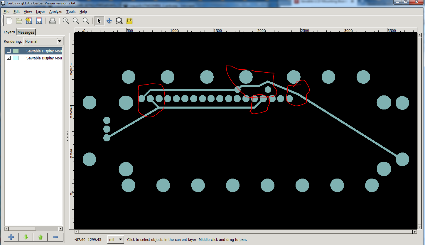
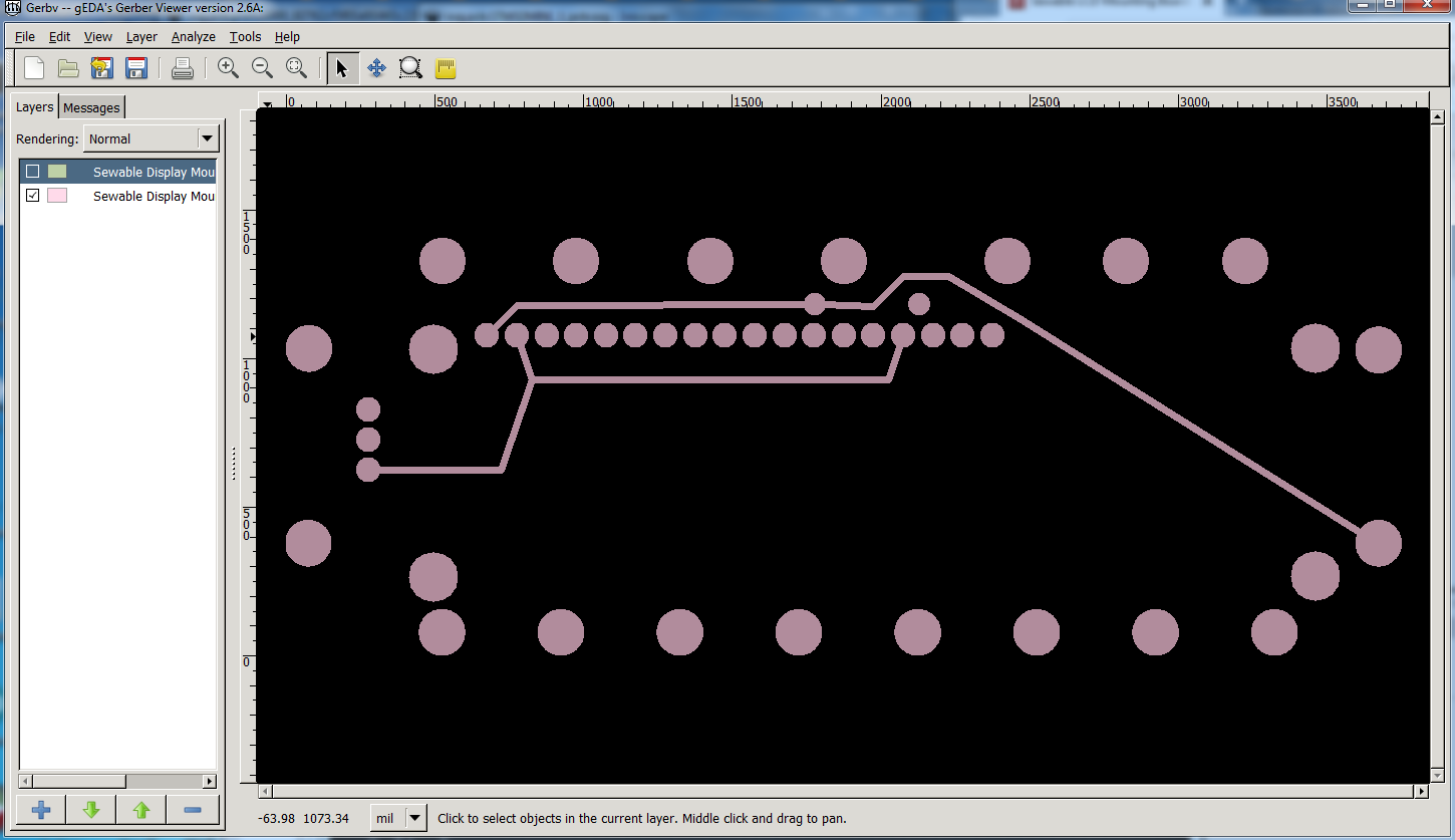
It will work just fine, DRC will complain and if that is the only complaint, ignore it. As noted anything beyond the edge of the board will get truncated. When you are all finished you want to export the gerbers (you need to to make boards anyway) via (File->Export->For Production->Extended gerber and then use a gerber viewer (I use gerbv) to look at what the board will be produced as. There are Fritzing bugs where it looks fine in pcb view but the gerbers are incorrect, and the gerbers are what the board will look like.
Fair enough, it will work fine either way, but pads on mounting holes reduce the room for traces, but in this case that isn’t an issue.
As long as the adapter doesn’t make the LCD higher that is likely a good solution. A change to the 3d print design may be easier than a change to the pcb and making new boards.
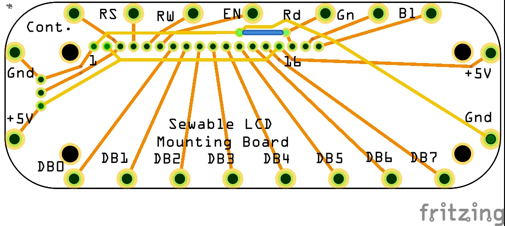
Both of the top mounting holes now align with an LCD array (I checked by clicking on one in the menu and superimposing). The lower ones can hold simple braces, or I can develop 3D-printed parts to extend south to the corresponding places on 2- or 4-line displays.
This much more real estate on the board allowed me to put more space between the sew holes; I even got all of the digital I/O along one edge, and added extra +5V and Ground sew holes (something I see often, and in this case it makes better sense for either left or right wrist wearing).
What’s left to do is figure out the measurement that RA headers would move the posts. It just occurred to me that, rather than move the mounting hole, I can just add a new set of header pads at the lower location; that would allow for either the RA headers, or short straight headers, depending on what’s available and what’s specifically needed.
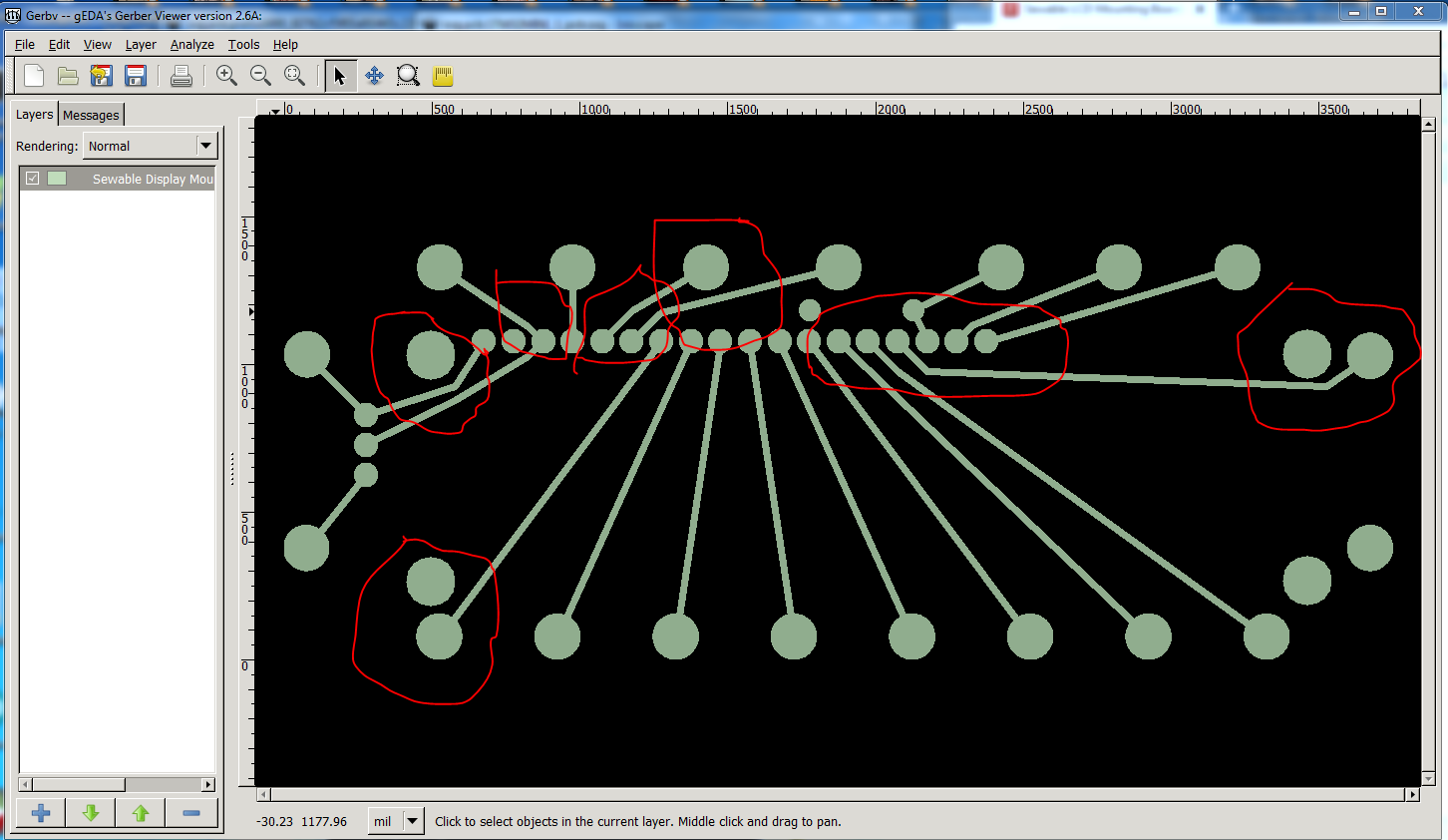
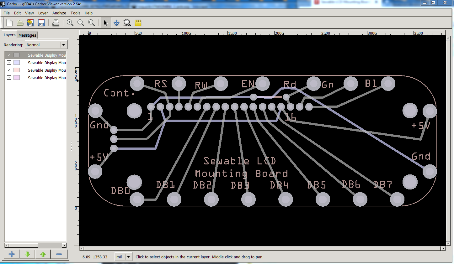
That worked, don’t know what happened with the first one. Looks good and would work as is, but I would increase your clearance in places because you have the room to do so. This is the copper bottom layer of the above fzz from gerbv:
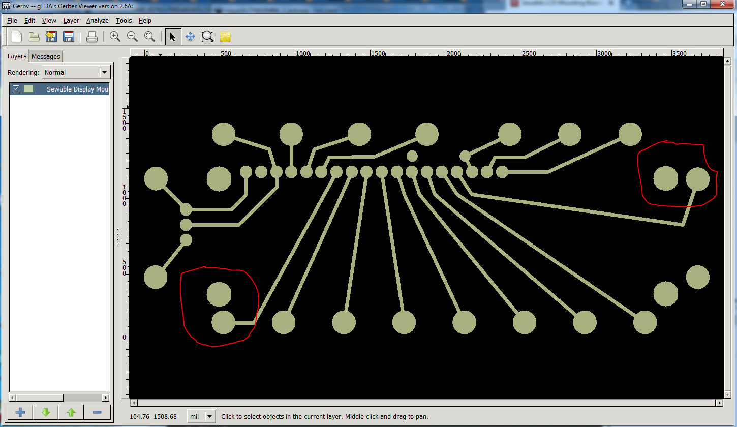
The red markers are places where I would reroute for more clearance. If possible (I didn’t do it here) I would move the sew pad by the bottom left mounting hole to provide more clearance for the mounting screw. Here is how I would route this:
edit: I see I missed one trace, so I corrected that and replaced this fzz, the circled trace in the top left is changed in this fzz to provide more clearance.
Here’s where you get to throw a fit, because about 90%% of what you just did is now undone. I managed to get the distance needed for the R/A headers much more easily than I’d anticipated.
I think the sew holes on the right end, and maybe the Contrast sew hole, are the only ones that still have the problems you cite, and I can fix those easily enough.
Not a problem, this is the normal course for laying out a pcb. Try something see if it works or doesn’t, then try and improve on it. Along the way some of the folks watching this may learn how to do it and everybody wins.
A late potential wrench in your plans. I was thinking about why you wanted RA headers, thinking that soldering in a standard low profile header would probably be as small or smaller, and realized you probably want the LCD to be unplugable (thus large .1 female sockets, and RA connectors to make them smaller.) There is an easier solution though, so called swiss sockets ( I have some but can’t find a reference to post at the moment) will do what you want with minimal space (I’d expect about the same space as a RA header. They need a 0.030 hole and are like the pins in a machined pin IC socket except in a SIP header format in both male and female. You would need to unsolder the .1 headers (which won’t mate with these sockets) on the LCD if it already has headers fitted but it may do what you want without the RA connectors.
edit:
Found what I mean on digikey (ebay has them cheaper but I can’t find a listing): A208-ND is an example digikey part number for the socket version (it has a picture so you can see the small size). There is a dual pin version like a .1 header as well but I searched for socket.
Coolness! I’ll take a look at that tomorrow. (The ability to unplug would be good, but it’s not a deal-breaker.)
And like I implied earlier (or at least tried to), I’m not doing much with it right away. I actually just had the problem in front of me and wasn’t going to rest well until I had a good idea of what mistakes I was making.
Yeah, it looks like something like this would be just the ticket, in actual practice. The good news is that, unless there’s something there that I’m missing, I wouldn’t even (necessarily) have to change the board’s design, for general use; it should fit fine as is. Great find, Peter! Thank you!
You may need to adjust the hole size down a bit, the pins on these are IC size (which Fritzing uses a 0.035in hole for rather than 0.038in. As I recall (I don’t have one to hand) there is a larger lip at the top of the pin I think meant to press fit them in to a plated through hole. In your case where height matters you probably want the hole big enough to allow that lip to fit in it to minimize the height. I also had problems finding any on ebay, there used to be some listings with 10 each male and female 140 strips for I think about $5 (I bought some 5 or 10 years ago) but I can’t find such a listing now (which may just be wrong search terms.) when a single strip of 150 was $6 from digikey (to be fair, I think the digi ones were gold and the ebay tin, but still …)
The Harwin pins I found (link above) don’t appear to have that issue, and $3.80 for a strip of 30 (since 16-18 would be needed for this project) doesn’t seem too bad. Plus, I can keep researching other brands for a lower price and better fit.