I’m (slowly) working on making some fixes to the parts factory code. As part of that I intend to fix the dual row header code which is currently broken in breadboard (it doesn’t generate a dual row header although it does in pcb). As part of finishing off the TM4C123GXL part I implemented a new layout in schematic which I intend on trying to make parts factory emit in the case of a dual row header:
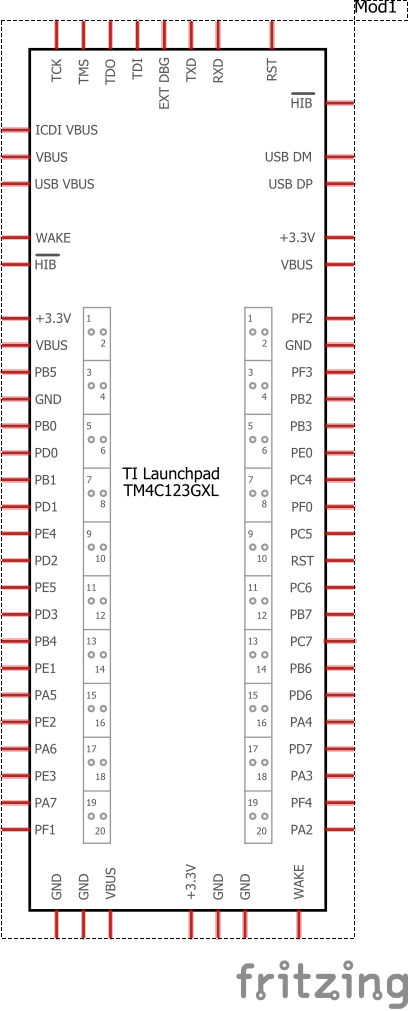
in this schematic the two center 20 pin connectors are dual row (manually done on breadboard). The change is the two drawings after the pin labels which show a picture of the actual connector and associate the schematic pins with their physical connection on the header. It may be necessary (or desirable) to be able to select whether the extra picture is there or not. I’m putting this here to see if anyone sees a problem that I am not with doing this. Comments are welcome. If you want to see this in an actual sketch, download the new TM4C123GXL part I just posted, that is where this schematic came from.
Peter