I am building a new part. There are 12 connectors (8 pin and 4 case, aka ground, connectors). On the PCB tab of the Parts Editor I have a pad to “Select Graphic” each connector to. In the Bread board view I only have 8 graphics to select since when working in breadboard format only the pins are of consequence.
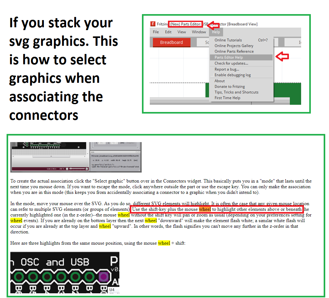
In the Parts Editor where do I “Select Graphic” the additional 4 case connectors to? I have seen other parts that have multiple graphics stacked in the SVG file but how do I single out each stacked graphics when selecting graphics?