Please help. Need a Fritzing part for this board:
Not enough information here to do anything with. I would need the web site of the board (there seem to be a few ESP32-S3 SuperMini boards, one from Waveshare and others) and I need the exact one you want with dimensions and connector information (only the connector information is here.)
Peter
Thanks Peter.
This isn’t a WaveShare board.
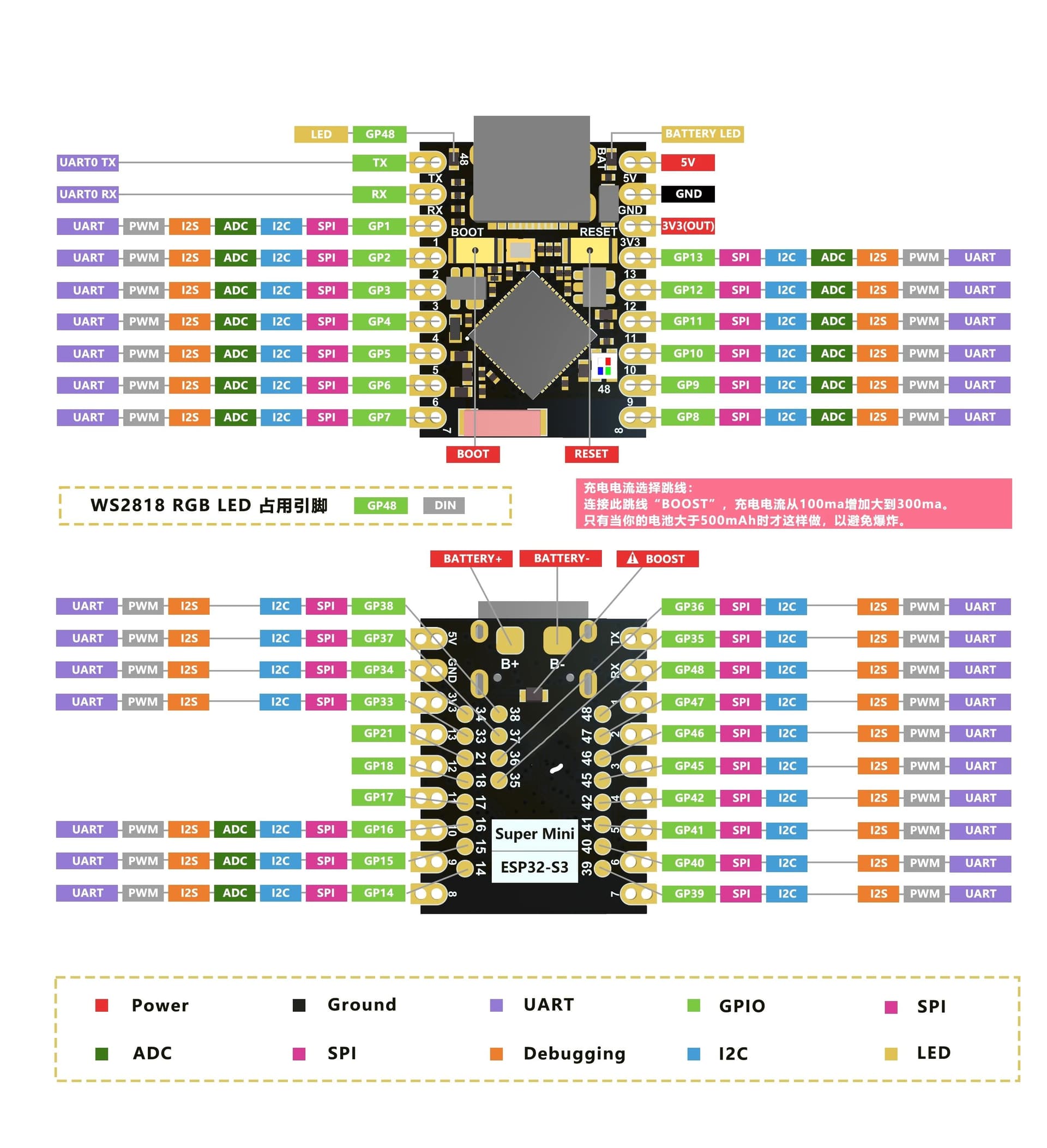
It’s the only S3 Supermini board I’ve seen with 9 pins on each side and 20 pads on the back in addition to the battery pads.
The system wouldn’t allow me to add a link on the original post but it did this time:
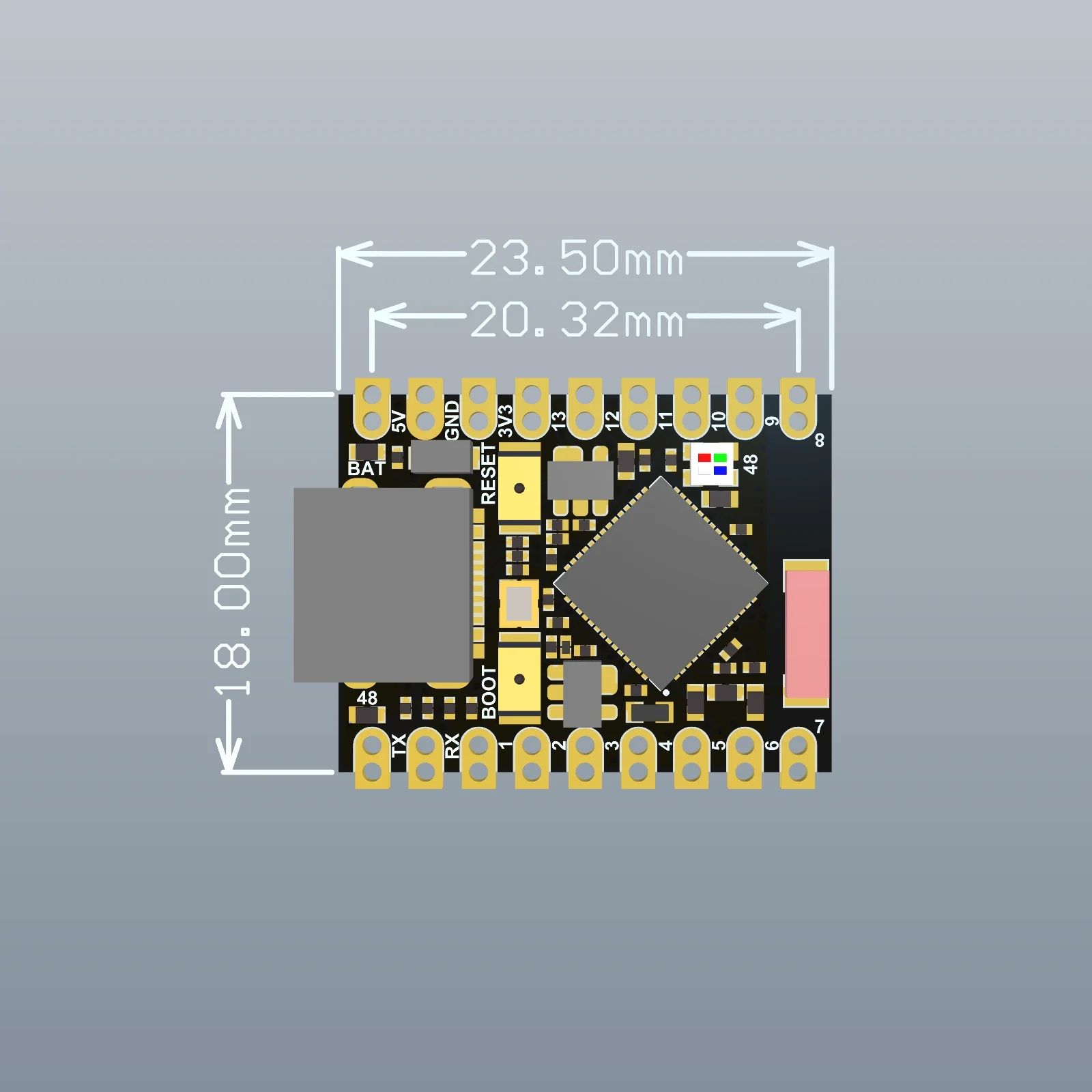
I was also able to add a second diagram this time (apparently, they don’t consider me a new user anymore?!?!):
That link is the place to start. From that I can make a part which will be up in a while. That has all the necessary information in one place or another.
Peter
Very cool! Thanks Peter!!!
OK here are two parts and lots of warnings ![]() . One part is through hole (the tht part) which is suitable for breadboard use but has the bottom layer pads in breadboard and schematic (but not pcb, you would need to solder wires on to use the bottom pads if you want to.) That makes breadboard rather odd as pads appear in the middle of components in breadboard but it works (the pads are also female so they won’t connect to the breadboard and cause shorts if you drag the part on to the breadboard.) The pad spacing is odd, so to get it to connect to the breadboard you may have to shut snap to grid off (or set it to a low value) so you can move the part til it connects.
. One part is through hole (the tht part) which is suitable for breadboard use but has the bottom layer pads in breadboard and schematic (but not pcb, you would need to solder wires on to use the bottom pads if you want to.) That makes breadboard rather odd as pads appear in the middle of components in breadboard but it works (the pads are also female so they won’t connect to the breadboard and cause shorts if you drag the part on to the breadboard.) The pad spacing is odd, so to get it to connect to the breadboard you may have to shut snap to grid off (or set it to a low value) so you can move the part til it connects.
esp32-S3-supermini-tht.fzpz (24.7 KB)
The other part is the smd version (where you solder it to the board and all pads are accessible in pcb.)
esp32-S3-supermini-smd.fzpz (24.8 KB)
pcb routing is quite exciting, but it will pass default DRC with enough effort
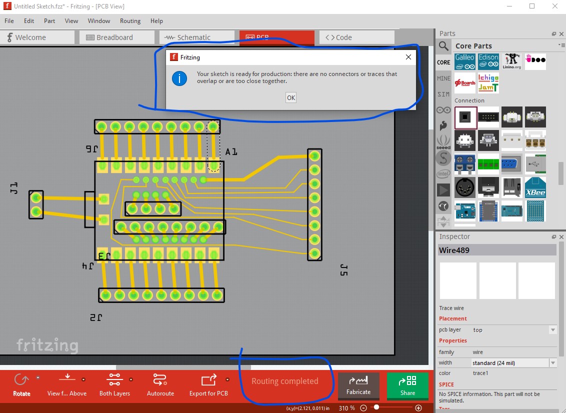
using 8mil traces and a 0.01in grid size. In real use vias to route the pads on the bottom of the board would be a better bet. As always (but especially in this case) before ordering boards print the pcb footprint out at 1:1 scale on transparency film for overhead projectors and compare it to a real board. The SMD pads were placed based on one of the jpgs on the site and may or may not be correctly placed (they may be close enough to work though.) If they are wrong it is easy enough to fix if you can supply how much and which way the pads need to move.
Peter
Wow! That works nicely.
Thanks very much Peter!
Hello,
I’m working on a robot project and i’ll use this board for my project.
so i have to use the SMD GPIO pins also as the other pins are not enough for my project.
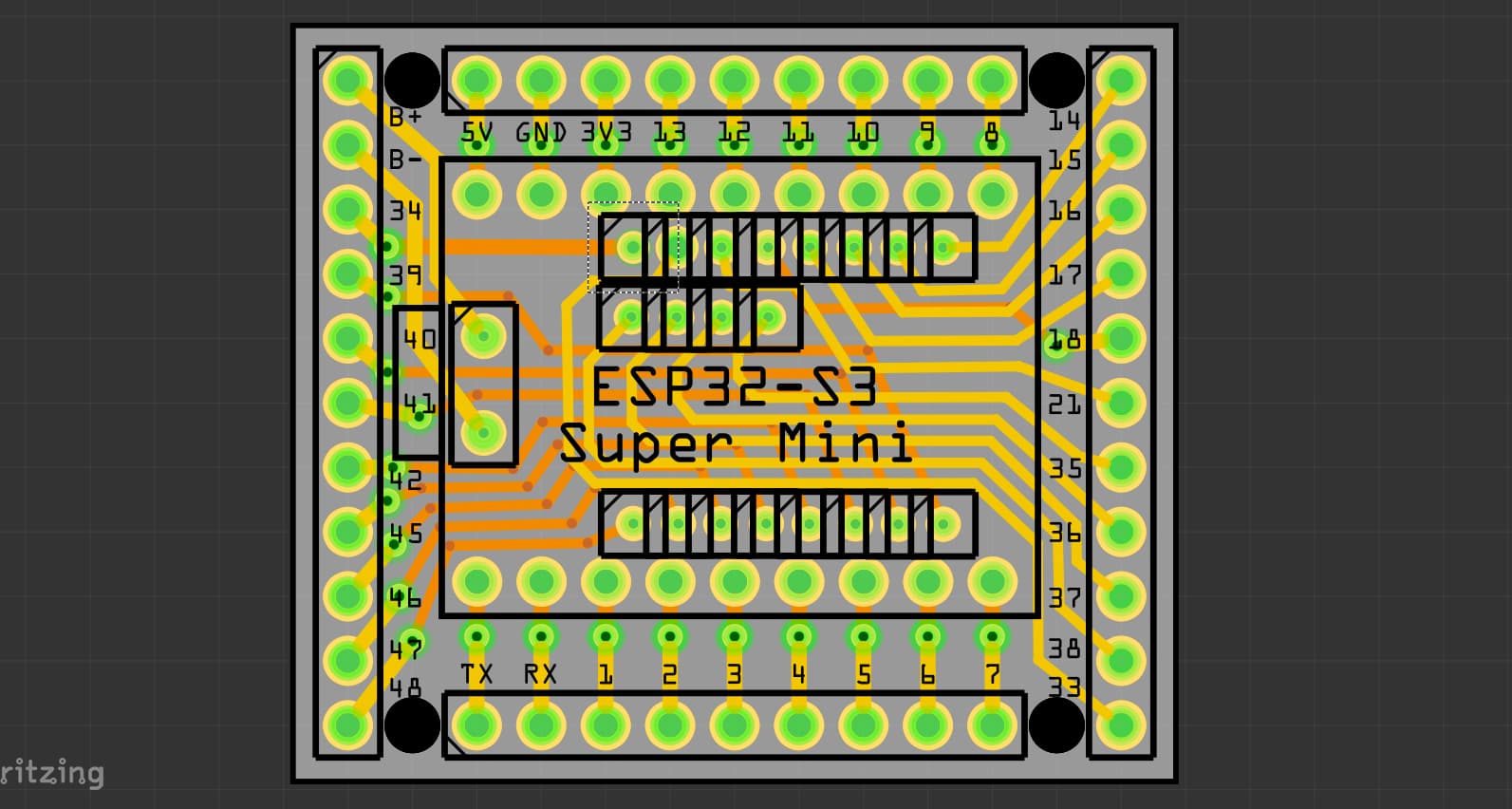
I’ve made a PCB design to transfer the SMD GPIO pins into easy accessible pin headers
here is my PCB :
esp32-s3-super-mini-shield.fzz (50.4 KB)
but the problem is : i don’t know how to connect the SMD pins to the PCB.
i tried searching for Pogo pins but i didn’t find any suitable size as the pads are too close to each other.
if you have any idea of how can i achieve the connection of the SMD pads to the PCB (preferably without soldering the board to pcb ) please let me know.
Thanks ![]()
A google search for pogo pins turns up a 1mm pogo pin (501-1827-ND) at digikey ($6 ea though) that should do as the pitch on the smd pads is about 1.8mm. There may be other cheaper ones available if you search.
edit:
amazon has .68mm diameter pogo pins at $11/100 which should do.
Peter