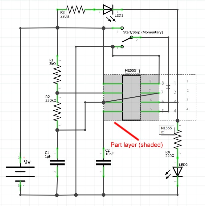
Somehow, my IC schematic symbol has ‘separated’ into two layers – ‘part’ layer and ‘text’ layer. I cannot get the text layer aligned with the part layer, so that the pin numbers (text layer) are ‘over’ the correct pins. Hopefully screenshot will explain/illustrate.
If you upload the sketch (the .fzz file) via the seventh icon on the left in the reply tool bar I will have a look. The likely answer is that you have caused database corruption by making changes in more than one view, but I’d need to see the sketch to be sure.
Yeah, there is some IC that go haywire each time you open the sketch/project, and every subsequent opening of the sketch moves it 1 step further away. I have some old sketches that I’m too lazy to fix, so you click on the IC, change the number of pins for the part in Inspector, and then change it back to the correct # of pins. This doesn’t fix it so you will have to do it each time you look at the sketch. Otherwise you need another part.
My thanks for your perspectives, gentlemen. I believe the attached file is what vanepp is requesting. If not, please advise. The export function did not show fzz as available export format, so I did a File/Save As. Obviously, I an a newbie!
I must say I am impressed with Fritzing. I have tried two other software products and could not get them to work. Fritzing is much more intuitive. Working with Visio and similar programs makes the Fritzing interface less intimidating.
Interesting! A new bug that I’ve never seen before. Am I correct in assuming that you created the 555 part you used by modifying a generic IC? There are a number of 555 parts available in core (with labels on all the pins being the main difference, yours should work too). You can find them by typing 555 in to the search bar in the parts bin (top right of the screen). As Old_Grey suggested, changing the pins from 8 to 10 then back in Inspector (the window on the bottom right, in the pins pull down menu) appears to fix it. Doing 10 pins instead of 6 preserves the connections when you switch back (doing 6 pins leaves 7 and 8 disconnected when you switch back requiring you to move them to get them to reconnect). I’ll poke at this as I get time and see if I can figure out what the bug is. You have started out correctly in any case. You are best to complete one view first and then use the rats nest lines to complete the other views. If you misconnect a component (putting it the wrong way around is a common one) it can corrupt the routing data base and require you to clear out all the connections and start again.
Thanks, I’ll see if I can figure out what is breaking. It is storing the change somewhere odd, as it isn’t in temp nor mine parts bins but is in the sketch and the output of the parts factory must be somewhere (and not correct).
Would you two mind speaking English?!? I ‘somewhat’ understand what you are talking about. Is there anything I should do at this point?
I have deleted and inserted the core 8-pin IC a couple times. and then struggled to correctly re-connect all the schematic links (wires). And if I remember correctly, all is fine and then WHAM!.. I do something or the drawing gets refreshed and the part/text layers are no longer tied together.
I am using the ‘libraries’ installed as part of the program installation. I’ve added no other drawing/design components.
OK, I’ll try to stick closer to English although that is somewhat difficult . The heart of the matter looks to be the generic IC. Fritzing creates them on request (as opposed to a normal part that it loads from a .fzpz file). In this case it hasn’t yet written the part to a fzpz file. That means it is storing it somewhere (and I don’t yet know where it is storing it) and something about that breaks the part when you reload it as part of the sketch. The easy way to avoid this bug is to use one of the predefined 555 parts in the core parts bin (the window on the top right). This is loaded from a .fzpz file and works fine without tickling this particular bug. If you want to use a generic IC (for instance because the part you want doesn’t exist in Fritzing yet) right click on the part and select Edit (new parts editor).
When the editor starts up, you don’t need to make any changes (although you can) but rather select file->Save as new part. That will put the part (as a .fzpz file) in your mine parts bin. From there you should be able to use it just like any other predefined part. If you are just starting with Fritzing you are probably better to use one of the 555 versions available in the core parts bin though. A tip that will help when you need to delete a part: if you choose “delete minus” instead of “delete” it will delete the part but leave the connecting wires in place so you can drag a new part in to place and then move the wires to reconnect them. Saves rerouting potentially many connections. Hopefully this was close enough to english, if not feel free to ask about parts that aren’t clear. Fritzing is relatively poorly documented, so most learning happens by asking questions here. You are on the latest released version (development has stalled and there hasn’t been a release in coming up on 3 years).
 I ‘somewhat’ understand what you are talking about. Is there anything I should do at this point?
 . The heart of the matter looks to be the generic IC. Fritzing creates them on request (as opposed to a normal part that it loads from a .fzpz file). In this case it hasn’t yet written the part to a fzpz file. That means it is storing it somewhere (and I don’t yet know where it is storing it) and something about that breaks the part when you reload it as part of the sketch. The easy way to avoid this bug is to use one of the predefined 555 parts in the core parts bin (the window on the top right). This is loaded from a .fzpz file and works fine without tickling this particular bug. If you want to use a generic IC (for instance because the part you want doesn’t exist in Fritzing yet) right click on the part and select Edit (new parts editor).