Hello There,
Wondering if someone has this part for 9DOF accelerometer MPU-9250 from Invensense.
Bangood has this breakout board.
I am asking if some one has the fritzing part for this board ?
Regards,
BusDev
Hello There,
Wondering if someone has this part for 9DOF accelerometer MPU-9250 from Invensense.
Bangood has this breakout board.
I am asking if some one has the fritzing part for this board ?
Regards,
BusDev
A google search for “fritzing part mpu-9250” indicates there is one in the Sparkfun fritzing part repo on github. If that isn’t suitable (the ebay et. al. clones are usually a copy), post again and I’ll look further.
Peter
Yes. I looked at Sparkfun board before posting here.
Unfortunately, it is looks dimensionally different to the one on AliEx or BG or ebay.
I cannot use the sparkfun part, Is it possible to get a part for this ?
Thanks,
Regards,
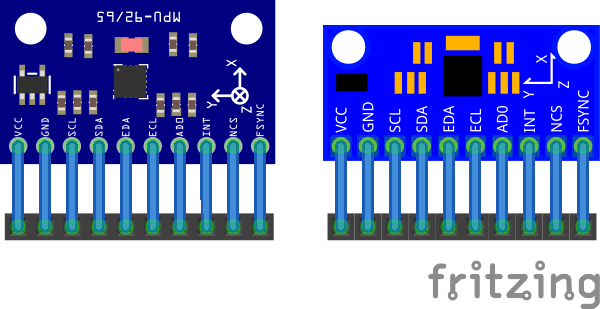
Indeed when I looked these are not like each other. This however is more like it (but lacks the size and proper placement of the mounting holes which is important in IMUs). If you could provide the correct locations and size of the holes I will update the part.
Edit: I just discovered I have two of these boards that I ordered from ebay but haven’t gotten to playing with yet. Thus I got out the calipers and fixed the positioning and am replacing this part.
gy9250.fzpz (13.8 KB)
Peter
Hi Vaneep,
I have a bunch of these coming on order.
Then i am going to take some physical measurements, and update here.
Till then your guess is my guess.
Btw, great work on turning this around in such short time.
From what i have seen so far on internet, these are dims [ to be validated]
Pin spacing: 2.54mm
Module size: 15mm * 25mm
Thanks,
Yep, knew those, its the position of the mounting holes and their size which is the mystery. As usual there doesn’t seem to be a mechanical drawing available on the Internet for these boards.
Peter
Yup got it. I got my calipers ready.
will let you know as soon as i can get my hands on one.
Hi there! First time poster and all that.
I have one of those breakout boards and used it to learn how to make parts for fritzing. I know my measurements aren’t 100%, but the pcb spacing should be correct as it is standard 0.1" spacing. I will be making a v2 that is much more accurate sometime soon.
Please check it out and let me know what you think.
Thanks
Randy
MPU 9250 Breakout.fzpz (10.0 KB)
Not at all bad, a few problems though. As noted as I replaced the part above I find I have two of these and calipered them and modified the part. Looks like you have a different board because mine is bigger:
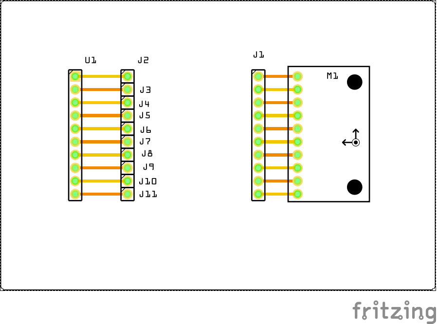
The breadboard svg is missing the layerId breadkboard group. The only thing I know that breaks is svg / pdf export. Your part won’t show up in such an export.
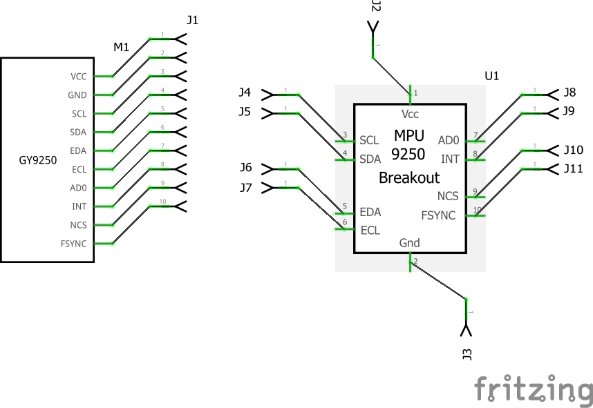
schematic has most of the problems:
The wires are connecting in the middle of the pin because the terminalId is missing in the schematic svg. That is typically a 10 thou square at the end of the pin (parts editor will add it for you if you are using parts editor, I rarely do though preferiring to eedit the files directly). I usually prefer to make schematic match breadboard to make debugging easier ( I can see where a pin goes in schematic without searching for the pin number), but either way is fine. Your way actually uses less space in schematic which i s a good thing on complex sketches.
pcb is file except it lacks the board outline so you can see where the board is sitting on the pcb so you don’t try and place components there. Note on my board the mounting holes are shown on silkscreen but not drilled. That way if the user wants mounting holes they can drag a hole from core parts over the silkscreen hole, and if they don’t want mounting holes they can route traces through that space.
finally the test sketch (which I used to make sure I hadn’t broken my part with the changes). The 45 degree connections in schematic catch terminalId problems. The check script complained about the lack of termanalIds in schematic but will be perfect;y happy with a terminalId going to the wrong pin (because it is there). This catches that case.
Peter
Hi Peter,
Thanks for the wonderful work.
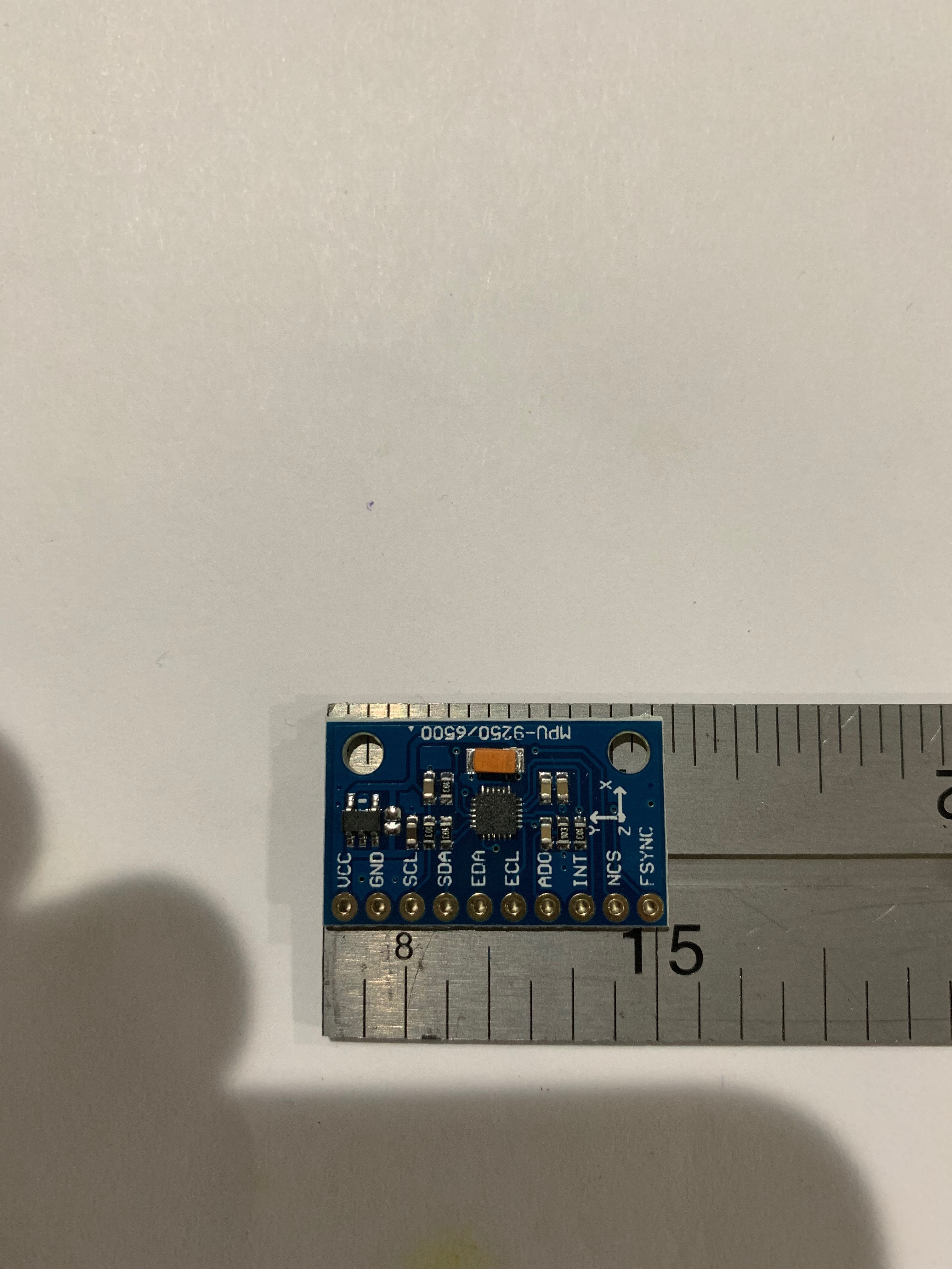
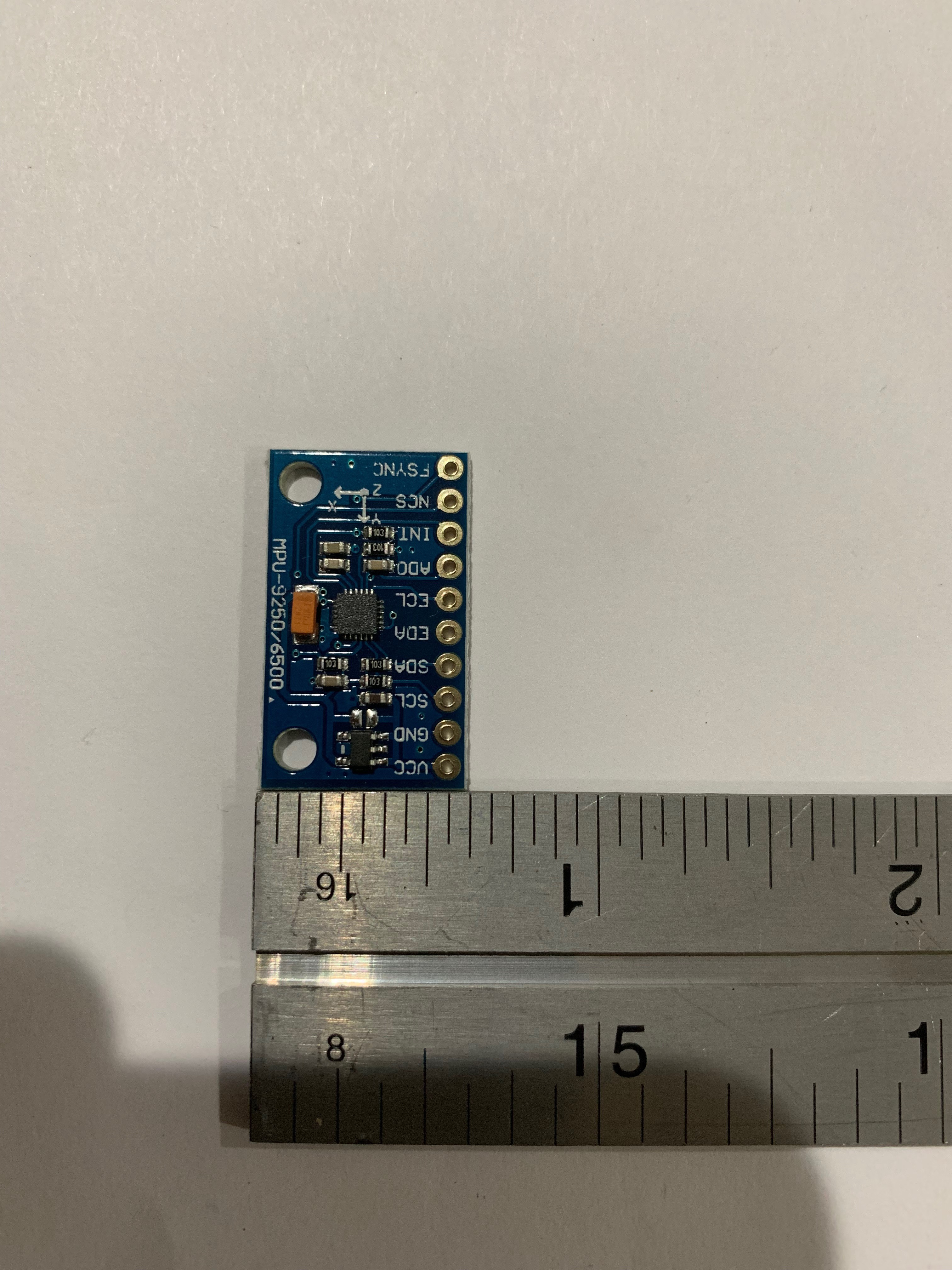
I did receive the parts, and took some measurements.
Its hard to find the hole-to-hole centers on such a small part, but i put them here anyways.
If there are any additional dimensions you are in need of, let me know.
The part checks out ok for 15mm x 25mm in general dims.
[Note i used an Inch ruler ! ].
Preformatted text
Regards,
Thanks Peter for looking over my part and your feedback.
My first part posted here is wrong, it was my first time using inkscape. I’ve corrected all the mistakes you pointed out, all but the terminalid problem. What’s the best (easiest) way to fix that? I mean, I’ve been into the .xml file in the part’s .fzpz, but I’m not sure how to correct that. I can edit the .xml file and put it back into the .fzpz file, but is there somewhere along the way that I could have fixed that? Like in inkscape or fritzing’s part editor?
Thanks,
Randy
Depends who you ask ![]() , my method (which not everyone approves of) is edit the underlying files because I can rarely get parts editor to work for me. The official way to do this is in parts editor select the pin and in connections set the terminal to east/west/south/north. What that does is create a terminalId entry in the fzp file and create a 10 thou by 10 thou rectangle on the end of the connector. I prefer to cut out the middle man and in Inkscape create a 10 thou by 10 thou rectangle call it connectorxtermainal (where x is the pin number as in connector0terminal) and move it to the end of the pin. Then in the fzp file if it doesn’t already have an attribute terminalId=“connnectorxterminal” in the schematic view connector line, add it. An example (with the carets removed as the forum doesn’t like them and tries to use them as markup …)
, my method (which not everyone approves of) is edit the underlying files because I can rarely get parts editor to work for me. The official way to do this is in parts editor select the pin and in connections set the terminal to east/west/south/north. What that does is create a terminalId entry in the fzp file and create a 10 thou by 10 thou rectangle on the end of the connector. I prefer to cut out the middle man and in Inkscape create a 10 thou by 10 thou rectangle call it connectorxtermainal (where x is the pin number as in connector0terminal) and move it to the end of the pin. Then in the fzp file if it doesn’t already have an attribute terminalId=“connnectorxterminal” in the schematic view connector line, add it. An example (with the carets removed as the forum doesn’t like them and tries to use them as markup …)
    schematicView
      p layer="schematic" svgId="connector0pin" terminalId="connector0terminal"/
    /schematicView
which ever way works best for you is good.
Peter