I’m trying to build a strobe - it used to be popular 30 years ago - to check ignition timing, but when I look for small transformers, 600V caps, Xenon bulbs, trigger transformers, there aren’t many, or at least a good selection, on Ebay/Ali or at my local store.
Go to your local thrift store or pawn shop and get some old film cameras with built in flashes. They have everything you need. You used to be able to go to photo finishing places and get the used disposable cameras with flashes for free.
I saw some strobe projects online using a camera flash, but I thought that they might not be readily availible to everyone.
What I’m trying to do is come up with a simple cheap circuit with easy to find parts so poeple can set their timing when trying to start their car using the Arduino ECU project - the whole project is about cheapness -. I found 1 circuit that doesn’t use many parts, so I’m testing that.
I have a simple LED timing light working, but it has problems and is rather weak. This one is cheap and only uses 11 easy to get parts, and if I can make it better I won’t worry about the Xenon strobe.
If you are using standard white LEDs (I’d be tempted to start from a 5 or 9 led ebay type battery flashlight to get the leds a case and reflector to get a directed beam that may be bright enough) you should (note the weasel word ) be able to get more brightness by increasing the voltage driving the LEDs to source more than their rated current with a short on long off cycle. Light output is linear with current (but at some current point the internal bonds may melt) and the short duty cycle keeps the heat (which is usually the real limiting factor) within bounds. The newer multi watt white leds I think use a phosfor to adjust the light output spectrum and thus may not turn off fast enough to do what you need (simulate the bright fast output of a strobe tube), but I think the standard 5mm type white leds that come directly from the die should probably work. You may need to drive it from a power MOSFET to get the current you need though.
As well I assume you have seen
That remined me that have an old junkshop 7 LED torch, but after testing it wasn’t that bright. I also have a new COB torch which is bright, but if phosphor has lag it’s probably not ideal.
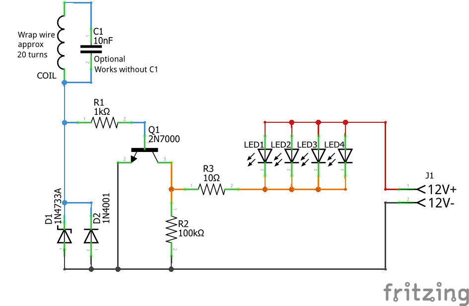
The circuit runs on 12V and only has a 10 ohm resistor, so I guess it’s already using a low duty cycle.
It’s hard to see in the video because the frame rate doesn’t match the strobe - eye was clearer - , but the Xenon TL showed the mark a touch below the dot on the VR sensor. The LED on the other hand was very close, but the problem is it showed 2 marks. One mark looked on the right spot, but the other looked about another 10º retarded - the vid kind-of shows the 2 marks -. Because it uses a wire wrapped around an ignition lead it must be retriggering with flyback. If you use the most advanced flash it should be good enough.
I’m going to try more LEDs, the 10mm LEDs, and I see if the COB has lag, when they get here.
replace the 1n4001 with a 1A schottky diode. The Schottky diode switches much faster than a 1n4001 which might help if it is the inverse spike that’s causing the second trigger.
Put a 50pf cap across R1 which will speed up charging the gate capacitance of the mosfet and make it switch faster (you may need to experiment with higher or lower values to see what works best)
Swap the 2n7000 for a higher current / lower RDSon value mosfet The 2n7000 is 5 to 6 ohms max RDSon (you still need the 3V gate threshold though). You look to maybe be drawing more than the max 500ma of drain current depending on what the LED voltage drops are. 15 ohms at 12V will be about 750 ma or so
With added circuit complexity you could also add a one shot at the junction of the diodes and R1 so you can stretch the length of the trigger pulse (a 555 timer should do) which may increase the amount of light you get if the current trigger is too short or it may not help at all but may be worth a try. Basically the coil/diodes trigger the 555 and its output drives the MOSFET for a fixed time. For testing a pot then allows you to stretch the pulse for more light output to see if it helps (or burns out the LEDs of course if it gets too long ).
The Schottky and cap are do-able, but I’ll have to research the MOSFET. I had a STP60NSO4Z working on the bench, but I had to switch to the 2N7000 because it wasn’t sensitive enough to trigger on the car.
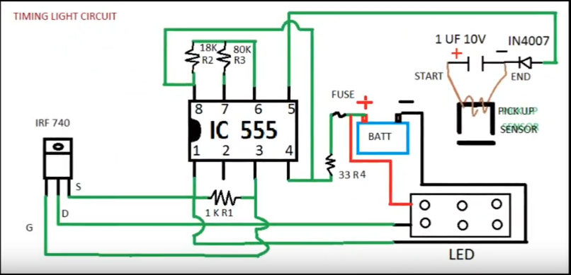
I tried this 555 from Ytube, but couldn’t get it to work.
I swiped the 555 circuit for a monostable from here (which also has the calculations for the r2/c3 values to set the monostable time which you will need to figure out):
The monostable triggers on a negative edge so you may need to invert the leads on L1 so that the leading edge of the spark pulse is going towards ground to get it to trigger correctly. I’d replace the 1n4001 diodes with 1n4148 switching diodes which are faster than the 4001s. They are there to keep the input voltage in to the 555 between ground and +12V to not blow the 555. Hopefully the current coil produces enough voltage (it will need about -8 volts to trigger I think, increasing the value of R3 may help if it won’t trigger as is). What this circuit does is stretch the input pulse width to being longer than the trigger, so you need to figure out what the maximum frequency of the input pulses will be at top revs and adjust the monostable pulse width to be about half of that. In theory that should get you more light (as the led is on a bit longer) and as a bonus should eliminate the second pulse if the monostable is set to stay on longer than the second trigger pulse when the spark goes off (assuming that is what is causing the two strobes which seems likely). You can replace R2 with a pot so you can set an approximate C3 value and vary the time with the pot to set the time experimentally. The ideal way to do this would be to have an oscilloscope where you can see the input waveform at the trigger on pin 2 of the 555 and the output from pin 3 on the 555 while doing the adjustments. As well this circuit will switch the MOSFET gate between 0 and 12V (so you need to make sure the mosfet has a max gate source voltage higher than 12V) but most any MOSFET should be driveable with this you don’t need a logic level mosfet as now. The drawing in the tutorial article shows how the output pulse is longer than the input trigger much better than I can explain in words .
Sorry L1 is only a single strand of open-ended wire that I wrapped 20x around the outside of the ignition lead and only gives out about 200mV on my Ebay DSO138 scope.
When I move D1 I see the wires are crossed, do I just rotate the diode - keep cathode to GND -. Timing_light_new2.fzz (11.0 KB)
My fault! I swapped the direction of the diode and screwed up the wiring. I hope the coil voltage level is because R3’s value is too low, I increased it to 470K which will need much less current to change the voltage and hopefully increase the voltage from the coil enough to trigger the 555. The input shouldn’t need very much current but it does need to get down to about 1/3 of 12v to trigger I think. If that doesn’t work we may need to add another resistor to ground from the trigger pin to get the DC bias closer to the trigger level so the pulse from the coil will trigger the 555. The idea of the two diodes is D2 will only let the input get to 12.6v at the trigger pin if the coil generated more than +12V and D1will only let the voltage at the trigger get to -0.6v if the coil gets below ground, they may not be needed if the coil doesn’t generate that much voltage. This sketch should be correct I think (or at least hope ). If this doesn’t trigger, please measure the voltage swing the coil produces at pin 2 of the 555 and I’ll try and figure out a resistor value that will let us trigger on what we get by biasing the trigger pin closer to the threshold. I’ve added (but not finished connecting) R4 in this sketch in case we need to try the dc bias trick.
Duh! I should have thought of that. Looks like the timer was triggered continuously and blew the led with 250ma of current. The 1 k will keep the current in bounds til we get this right (or decide we can’t whichever comes first ).
The output stage on the 555 is totem pole as far as I know so shouldn’t need a pull down resistor (it actively drives both high and low). From what happened I think the timer was continuously triggered, the 555 output was always high and the led was always on (and then poof as noted above from too much current). The 1K resistor in place of the 10 ohm should fix that while we figure out our trigger problems. For now I’d reproduce the circuit in the tutorial I started from to check the trigger does what we expect. So for testing replace the coil with a push button switch as in this schematic. That should let us verify the circuit does what we expect and set the timing values you want to adjust R2/C3 so the output pulse is a little longer than the pulse from the coil on your scope. When you push the button it should produce an output pulse that delays a bit when the button is released. If it doesn’t do that then there is something wrong with the circuit. Once we get that part working then we need to figure out how to trigger it from the coil (which may need the optional pull down resistor on the coil shown in my last sketch). I deleted the diodes for simplicity (if they are already there it is all right to leave them in as they shouldn’t hurt anything assuming I got the polarity right which may also be the source of the problem if I didn’t ) as without the coil they aren’t needed. With the button not pushed the led should be off. Pushing the button should turn the led on and keep it on briefly after the button is released.
It seams to be latching. I’m using a wire as a switch and when I close it the LED goes on, but when I open it it stays on.
EDIT
After playing for a while the 555 caught fire, so I tried another and it flashed the LED once and stopped working. 2 more blown 555s and I put the diodes back, and this 555 looks like it turns the LED on and off instantaneously - no lag - with the wire switch.
Back to my old 80s 555(tested in my simply osc circuit) and it latches, but another 80s 555(tested in my simply osc circuit) does the on and off instantaneously.
The Ebay 555 could be fakes, but it seams thay they latch or don’t delay the off.
EDIT EDIT
The working Ebay 555 blew so back to the latching 555, and now if I tap the wire quickly to GND it flashes a little. I think I have to get some new 555s of better quality.
For testing you may want to try something like a 10uf cap as C3 (plus towards pin 6/7) and 47K as R2 to give you a long time constant (around .5 sec) of output pulse. Then a tap on the trigger should give you a fairly long led on time before it goes off. With a short output pulse it may be hard to tell if it is working or not (although it does sound like you have some bad 555s).
I got some new TI 555s and had to use 100uf for C3, but only the first press has a delay. You press it the 1st time and it stays on for 3 sec, but any press after that and it’s instantaneous again. You have to dissconnect the power and reconnect, and it does the 1st press delay and 2nd instantaneous again. I tried holding the button on longer, to maybe charge the cap, but it makes no difference.
That would indicate that pin 7 (discharge) isn’t working. When the output goes low again (and the LED goes off) pin 7 should go to ground and discharge C3 to prepare for the next cycle. For some reason that isn’t happening. It may be worth putting your scope on pin 6/7 and see if the waveform there looks like the diagram in the tutorial (I suspect C3 is staying charged from the symptoms) . I’ll see if I can find a 555 around here somewhere to experiment with.
Damn, cheap Ebay parts caught me out again. Last year I made a circuit on a BB that didn’t work and after a lot of struggling I traced to the short blue wires that came in the Arduino kit, which had resistance , so I stopped using blue. I used a green for this one, but I thought I better change it out just incase, because it links pin 6 to 7. Looks like that fixed it because it now delays all the time.