Hi all, this may sound like a daft question, but I don’t ask I will never know. Is it possible for someone to read a code/sketch and design/create a Fritzing breadboard image, and if so where would I start looking (willing to pay for this service). Many thanks Terry
So if I understand this correctly, you’d like someone to assimilate someones code/sketch. Then build a circuit for you via the breadboard feature?
What are you trying to accomplish? Someone has a schematic/board already if there is a code/sketch. I’m just assuming. Maybe post that information too?
[quote=“landracer, post:2, topic:2798, full:true”]
So if I understand this correctly, you’d like someone to assimilate someones code/sketch. Then build a circuit for you via the breadboard feature?[/quote]
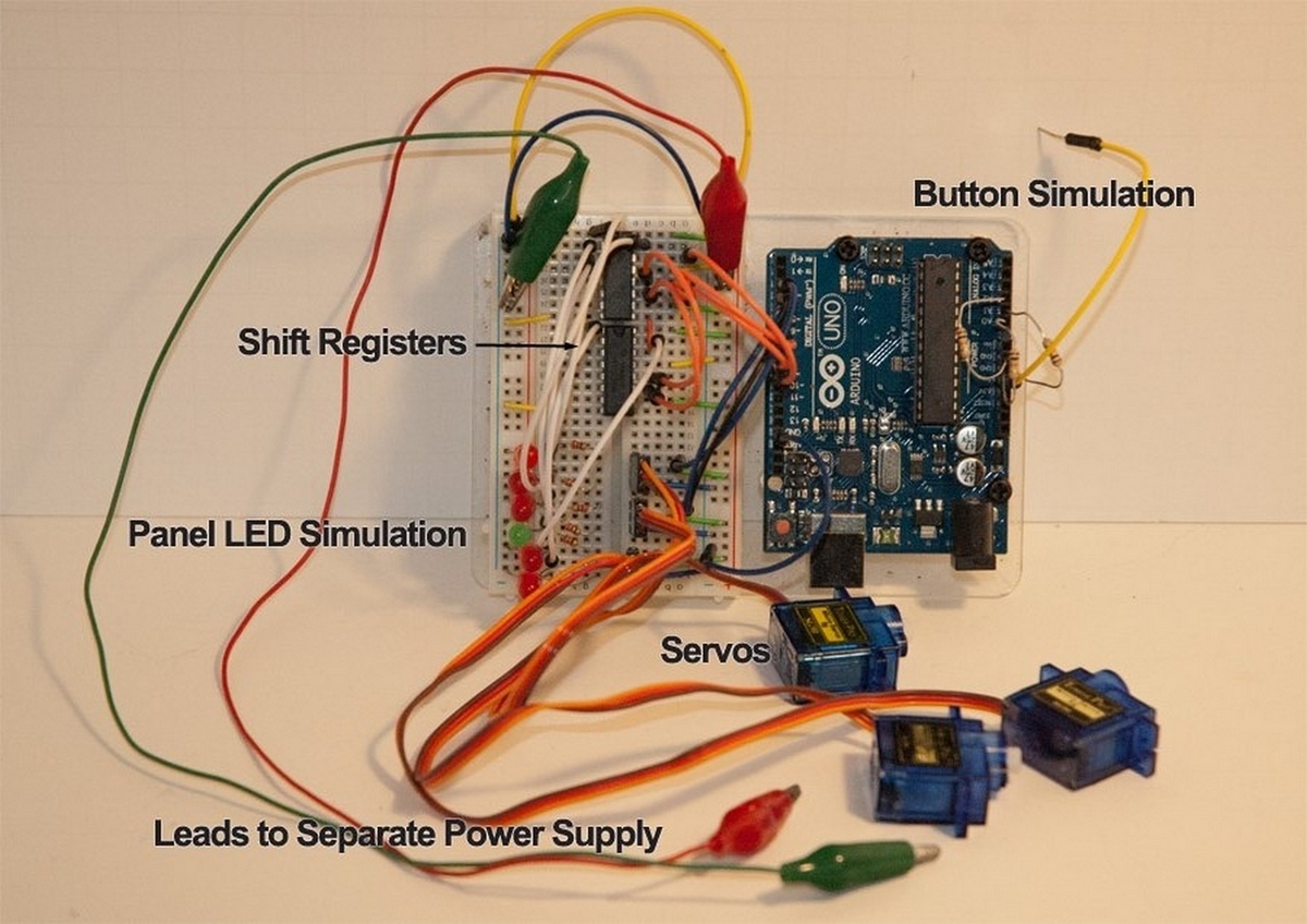
Hi landracer, The short answer is “yes”, I found the code on the internet and have been trying to contact the author, but have had no success,The Code/Sketch involves Servo’s, LEDs and push buttons for a model railway project using a Arduino UNO,not sure if this is the right way to post code, I’m sure someone will tell me;
#include <Servo.h> // include the Servo library
////////////////////////////////////////
//
// Definitions
//
////////////////////////////////////////
////////////////////////////////////////
// Basic parameters; adjust for your actual setup
#define NUMBER_OF_TURNOUTS 5
#define NUMBER_OF_SHIFT_REGISTERS 3
#define STEP_DELAY 70 // servo movement step delay, in milliseconds
///////////////////////////////////////
///////////////////////////////////////
// Data Structures
///////////////////////////////////////
//////////////////////////////////////
// TURNOUT_DEF holds all configuration
// information about turnouts and panel LEDS
//////////////////////////////////////
typedef struct TURNOUT_DEF {
uint8_t button_pin; // Digital or analog pin for the button associated with this turnout
uint8_t servo_pin; // Digital pin for the servo associated with this turnout
int pos_main; // servo position for the MAIN leg, in degrees
int pos_div; // servo position for the DIVERGENT leg, in degrees
int panel_LED_main_green; // The position(s)of panel LEDS in the shift register chain
int panel_LED_main_red; // Example assumes a bi-color (red/green) LED for each turnout leg
int panel_LED_div_green; // modify these elements to reflect the actual LEDS you are using
int panel_LED_div_red;
};
/////////////////////////////////////
// TURNOUT_DATA is wrapper structure holding
// both configuration and runtime data for turnout operation
/////////////////////////////////////
typedef struct TURNOUT_DATA {
TURNOUT_DEF data; // configuration
bool is_moving;
byte alignment;
int pos_now;
int target_pos;
unsigned long last_move;
};
// Alignment state values
#define ALIGN_NONE 0
#define ALIGN_MAIN 1
#define ALIGN_DIVERGENT 2
// pin ids for shift register chain controlling panel LEDS
#define LATCH_PIN 7
#define CLOCK_PIN 8
#define DATA_PIN 9
//////////////////////////////////////////
//
// Global variables
//
//////////////////////////////////////////
//////////////////////////////////////////
// TURNOUT_DATA Array
// * A0, A1, etc refer to analog pins which are used for buttons in this example
// * Replace pos_main (93) and pos_div (117) with real values for each turnout
// * LEDS are identified by their output position in the shift register chain;
// the identifier is a number between 0 and (NUMBER_OF_SHIFT_REGISTERS * 8) - 1.
// Example assumes LEDS are connected to shift register outputs sequentially
// from the first output of first register. You can connect LEDS to any output in
// any order; just set the identifiers accordingly.
//
// Only the TURNOUT_DEF part of the TURNOUT_DATA structure has to be initialized here;
// The remaining elements are managed internally and are initialized automatically
//////////////////////////////////////////
TURNOUT_DATA turnouts[NUMBER_OF_TURNOUTS] = {
{{A0, 2, 93, 117, 0, 1, 2, 3}},
{{A1, 3, 93, 117, 4, 5, 6, 7}},
{{A2, 4, 93, 117, 8, 9, 10, 11}},
{{A3, 5, 93, 117, 12, 13, 14, 15}},
{{A4, 6, 93, 117, 16, 17, 18, 19}}
};
// servo objects
Servo servos[NUMBER_OF_TURNOUTS];
// array to hold shift register state bytes
byte panel_LEDS[NUMBER_OF_SHIFT_REGISTERS];
void setup()
{
// Setup pins for shift register chain
pinMode(LATCH_PIN, OUTPUT);
pinMode(CLOCK_PIN, OUTPUT);
pinMode(DATA_PIN, OUTPUT);
// initialize each turnout
for(int i = 0; i < NUMBER_OF_TURNOUTS; i++){
// attach the servo
servos[i].attach(turnouts[i].data.servo_pin);
// set the pin mode for the button pin
pinMode(turnouts[i].data.button_pin, INPUT);
// test and position the turnout by moving
// to divergent then to main positions
servos[i].write(turnouts[i].data.pos_div);
turnouts[i].pos_now = turnouts[i].data.pos_div;
setTurnout(i, ALIGN_MAIN);
}
} // end of setup
void loop()
{
// get elapsed milliseconds at loop start
unsigned long currentMillis = millis();
// loop through the turnouts array
for(int i = 0; i < NUMBER_OF_TURNOUTS; i++){
if (turnouts[i].is_moving) {
// if sufficient time has elapsed since the last move
if ( (currentMillis - turnouts[i].last_move) >= STEP_DELAY ) {
// move the turnout one degree
turnouts[i].last_move = currentMillis;
if (turnouts[i].pos_now < turnouts[i].target_pos) { // if the new angle is higher
servos[i].write(++turnouts[i].pos_now);
} else { // otherwise the new angle is equal or lower
if (turnouts[i].pos_now != turnouts[i].target_pos) { // not already at destination
servos[i].write(–turnouts[i].pos_now);
}
}
}
// if target position reached, stop turnout motion
if (turnouts[i].pos_now == turnouts[i].target_pos) {
turnouts[i].is_moving = false;
turnouts[i].last_move = 0;
setIndicators(i);
}
} else {
// if a turnout is NOT in motion, check to see if its button is pressed
int button_state = digitalRead(turnouts[i].data.button_pin);
if(button_state == HIGH){
// toggle position
if(turnouts[i].alignment == ALIGN_MAIN){
setTurnout(i, ALIGN_DIVERGENT);
} else {
setTurnout(i, ALIGN_MAIN);
}
}
}
}
}// end of main loop
////////////////////////////////////////////////////////////////
// Supporting Functions
////////////////////////////////////////////////////////////////
void setTurnout(int id, int align){
// Set indicators to show turnout in motion
turnouts[id].alignment = ALIGN_NONE;
setIndicators(id);
// Set values to trigger motion on next loop iteration
switch(align){
case ALIGN_MAIN:
turnouts[id].is_moving = true;
turnouts[id].last_move = 0;
turnouts[id].target_pos = turnouts[id].data.pos_main;
turnouts[id].alignment = ALIGN_MAIN;
break;
case ALIGN_DIVERGENT:
turnouts[id].is_moving = true;
turnouts[id].last_move = 0;
turnouts[id].target_pos = turnouts[id].data.pos_div;
turnouts[id].alignment = ALIGN_DIVERGENT;
break;
}
}
void setIndicators(int id){
switch(turnouts[id].alignment){
case ALIGN_NONE: // means the turnout is in motion and not aligned
panelWrite(turnouts[id].data.panel_LED_main_red, HIGH);
panelWrite(turnouts[id].data.panel_LED_main_green, LOW);
panelWrite(turnouts[id].data.panel_LED_div_red, HIGH);
panelWrite(turnouts[id].data.panel_LED_div_green, LOW);
break;
case ALIGN_MAIN:
panelWrite(turnouts[id].data.panel_LED_div_green, LOW);
panelWrite(turnouts[id].data.panel_LED_div_red, HIGH);
panelWrite(turnouts[id].data.panel_LED_main_green, HIGH);
panelWrite(turnouts[id].data.panel_LED_main_red, LOW);
break;
case ALIGN_DIVERGENT:
panelWrite(turnouts[id].data.panel_LED_div_green, HIGH);
panelWrite(turnouts[id].data.panel_LED_div_red, LOW);
panelWrite(turnouts[id].data.panel_LED_main_green, LOW);
panelWrite(turnouts[id].data.panel_LED_main_red, HIGH);
break;
}
}
/////////////////////////////////////////////////
// Shift Register Functions
/////////////////////////////////////////////////
void panelWrite(int id, byte state) {
int reg = floor(id / 8);
int pos = id % 8;
bitWrite(panel_LEDS[reg], pos, state);
panelRefresh();
}
void panelRefresh(){
// Prepare to shift by turning off the output
digitalWrite(LATCH_PIN, LOW);
// shift all bits out in MSB (most significant bit first) order
for(int i = (NUMBER_OF_SHIFT_REGISTERS - 1); i>=0; i–) {
// shift out the bits
shiftOut(DATA_PIN, CLOCK_PIN, MSBFIRST, panel_LEDS[i]);
}
// turn on the output to activate
digitalWrite(LATCH_PIN, HIGH);
}
Regards Terry
Yes it looks possible to recreate the hardware for this from the code. I’m assuming you don’t have a diagram or an example for the hardware just the code and that’s why you are asking? This appears to want some (3 in this example) 74hc595 shift registers to drive the leds some push buttons (5 here) one to a pin to toggle the position of the switches (I assume a trunout is another name for a switch in modelrailroadese) and some servos (5 here one for each switch) . All the parts exist in Fritzing so it is fairly trivial to create this. The only thing unclear to me is why 3 shift registers, and why 4 values (I think because there are 2 leds one for each direction of the switch to act as signals) which would mean 10 leds in total.
TURNOUT_DATA turnouts[NUMBER_OF_TURNOUTS] = {
{{A0, 2, 93, 117, 0, 1, 2, 3}},
I think the end 4 numbers (0 to 3) are led positions in the shift register, presumably red green green red 2 for each position of the switch. Based on that this sketch implements (or is at least close to) the hardware this is expecting. I only did schematic not breadboard although I could do breadboard if you can’t figure it out as well. The 220 ohm led resistor values may need to change up or down depending on what leds you are using (if you proceed feel free to post what leds you are using an I can calculate appropriate values for you. The polarity may be wrong as well if he assumed common cathode, changing the sketch would be the easy fix to that. Enjoy 
switch.fzz (39.9 KB)
Hi vanepp, thank you very much for your reply, the only diagram I have is a jpeg image of a photo (find Attached), I think the 3rd shift register was added for future expansion, it needs 2 because I think 1 will only operate 8 LEDs not the 10 needed for 5 pairs of servo’s & push buttons.
A brief operating description of what I think code/sketch should do;
-
Load code/sketch from computer to UNO; The servo will go to 90 degrees and 1st LED will light up.
-
Press the button; The 1st LED will go off and the servo will move 20 degrees to 110 degrees and the 2nd LED will light up.
-
Press the button; The 2nd LED will go off and the servo will move 20 degrees from 110 degrees to 90 degrees and the 1st LED will light up.
Yes Turnouts/Switches/points are all one of the same thing.
In my operating description above is for single colour (green) whereas I think the Author is thinking of using Bi-colour LEDs Green/Red (I don’t know if 2 74HC595 Shift Registers will operate 10 bi LEDs or doe’s it turn 10 into 20 needing the 3? ).
Sorry I don’t understand “why 4 values”
I hope I am not asking to much but would you mind doing a breadboard?
The LEDs I will probably be using are (http://www.ebay.co.uk/itm/50x-3mm-Common-Anode-Bi-color-Red-Green-Light-Emitting-Diode-LED-Bulb-/121454788421?hash=item1c4744ff45:g:w1UAAOSw4shX9bW6
Or single colour “green” (http://www.ebay.co.uk/itm/222123297794?_trksid=p2060353.m2749.l2649&ssPageName=STRK%3AMEBIDX%3AIT ).
Again your help is very much appreciated. Regards Terry .
[I hope I am not asking to much but would you mind doing a breadboard?]
Hi vanepp. Can you hold up doing the breadboard as I have had a good look and tinkered about a bit and I think I might be able do it myself from your Schematic, will let you know how I get on. Regards Terry
Hi all, what a very impressive piece of software, tomorrow I will find out if works,Terry
switch 1.fzz (68.2 KB)
Looks like you pretty much have it in hand and yes Fritzing (even with its bugs) is impressive. The 4 values comment relates to what I think the leds are intended for. Each servo seems to have 2 leds (4 colors) rather than just one. I think the intent is that the leds go in a signal by the tracks at the switch one on each possible branch. If the switch is set to that branch the led would be green and on the other branch the led would be red (to indicate that you shouldn’t proceed). That seems to me why the numbers are there and why he needed 3 shift registers. If you don’t want to do that you can probably use less leds and at least one less shift register. Your leds are the typical Ebay type, no real information  but at least cheap so you may need to experiment with the 220 ohm resister values. You may want to start with something like 470 ohms and see how bright the led is. A higher resistor value will make the leds less bright and a lower value (within reason because too much current will damage the leds) will make it brighter. I think your analysis of the code is correct, at startup it cycles all the servos and then waits for you to push a button and then changes the position of the switch. You may need to adjust the two values (currently 93 and 117) to get your particular servo to move the correct distance. If you run in to problems, post and I’ll try and help.
Hi all/vanepp, I am about 90% through putting the breadboard together,
1st problem is the LEDs, should the centre pin go to ground not positive as in the circuit (the LEDs I am using are bi/colour red/green and the resistor is beige body with cream/purple/black/gold rings)
2nd Push buttons, am I right in thinking that the top right-hand switch with ochre & white wire are joined so when the button is pressed it joins all 3 ochre/white & black.
Terry
There are two led types common anode (which I used) and common cathode (which may be what you have).
If your leds are common cathode then yes the drawing needs to be the reverse the led common to ground instead of +5 volts. Assuming cream is yellow then this would be a 470 ohm resistor which should be fine. To figure out which way the leds need to be connect the middle lead to ground and the other lead to the 470 ohm resistor with the second lead of the resistor connected to 5V if the led lights red or green then you are correct the middle lead needs to connect to ground. For the buttons one contact from each needs to go to ground (and that will be a daisy chain of however many buttons you have) but the other contact should connect only to the 10k resistor and to a separate pin on the Uno. When the button isn’t pushed the uno pin will be at 5V (through the resistor), and when the button is pushed the uno pin will be at gound (and the resistor will prevent the switch from shorting the power supply which would be a bad thing ). The uno can then read the pin and decide if the button is pushed or not.
Hi vanepp, thanks for the explanation on the leds & buttons, I have ordered some common anode bi/leds that should sort that problem out. I was finding building the breadboard with everything on it very daunting (worse than overhead view of spaghetti junction) so I reduced your schematic to show only 1 servo, button & led, (find attached) and build the breadboard from that, and pleased to say it nearly works perfectly.
Is it possible to reverse the button; (unless my wiring is wrong)
When I loaded the code, everything was fine ( I am us 2 single anode leds as if it were a bi/anode led ), One led came on and the servo kept on sweeping through its cycle (back & forward), so I pressed the button and it stopped at the end of the cycle and the other led came on, I released the button and the servo started to move in the opposite direction and after about a second I pressed and held it down and stopped at the end of its cycle and the other led came on. so everything worked fine apart from the button being the wrong way round, Terry
schematic update.fzz (21.8 KB)
I expect that he used normally closed push buttons (rather than the more usual normally open that my schematic used and you appear to have). The easiest fix is to replace the HIGH in the code above with LOW as below:
// if a turnout is NOT in motion, check to see if its button is pressed
int button_state = digitalRead(turnouts[i].data.button_pin);
if(button_state == LOW){
// toggle position
which should make your button work without changes. You would need to change the push buttons you have with one that is normally open (or change to the NC connection if your push button has both) to make the change in the circuit and the software change is easier and cheaper I expect. Your common cathode leds should work if you change the common point from +5V to ground. I think that HC cmos should drive either direction (although I can’t say that I’ve tried it) and you may need to change some constants in the code to get the leds to light in the expected manner but that may be faster than waiting for new leds from ebay ![]()
Hi vanepp, your an absolute STAR, changing the high to low has done the trick,I will wait for the new leds to arrive, there’s lots more to be getting on with, again many thanks Terry