Here is an improved
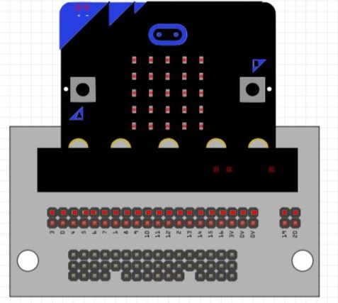
Micro:bit part. This one has schematic and pcb as well as breadboard. Pcb uses an edge connector (because that is how the Micro:bit connects) to connect to the pcb.
edit: I just replaced this with a newer version of the part which has been created as a board and tested.
I’m looking for an edge connector to import in Fritzing. I’m new, so I want to check if I’m right when I don’t see an edge connector in the file you shared. Can you help me out?
Edge connectors in Fritzing are complex. While there isn’t a specific part for the edge connector at the moment it would be easy enough to convert the MicroBit part to just the edge connector if desired (pcb is already there, just bb and schematic need to change). I just uploaded a newer version of the MicroBit part and there is a howto on how to make edge connector parts in Fritzing in the howtos section of the forum (although it assumes a lot of knowledge or parts creation). If you are aiming at a Microbit, I’d suggest just using this part (the edge connector is extra strange because if internal connections for the Microbit), if you need just the edge connector for something else I can make a part that is only the edge connector easily enough.
Ah! This explains what you need. I was looking at pcb thinking you wanted to make boards, but what you need is a breakout board showing in breadboard rather than the MicroBit. I can create a part with the breakout pinout as shown in a few hours I expect. Do you want the MicroBit attached to the breakout, or just the header connectors as shown above?
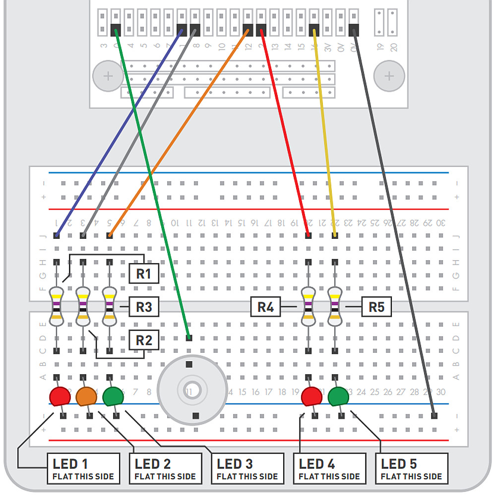
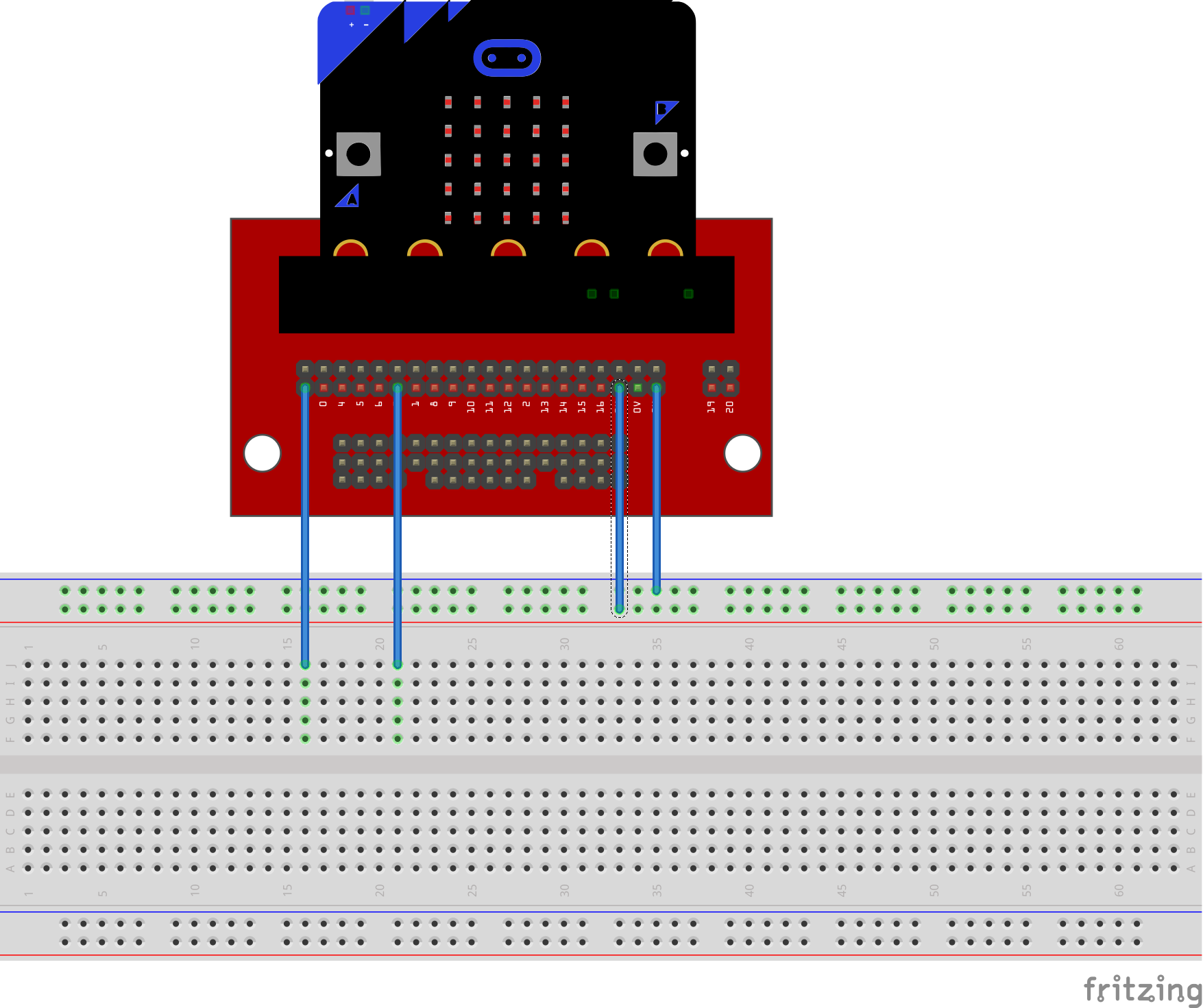
OK while this is lightly tested and not a complete part, I think it will do what you want. The only pins that are active are the one row by the numbers. The row above that should probably be bused to the active row but I didn’t do that and all the other pins are cosmetic. However if you load this part in to a sketch and connect it as the jpg above in breadboard it will reflect correctly in to schematic and pcb.
Thank you very much! Don’t know if you live in Belgium, but if you would live in the neighborhood I would by you a beer!
If it aint to much troubles you may change the color brown to light gray (like the breadboard) and the text and pins black. But only if it’s not to much troubles. Or can I change it myself? How? In Inkscape?
Unfortunately I’m on the west coast of Canada, so likely no beer . I’ve made most of the requested changes, the pins are a problem though. Fritzing changes the active pin area to red, and that can’t be changed (as you will see from the svg the pins are really gold).
Edit: replace with a part which will load beside the original one.
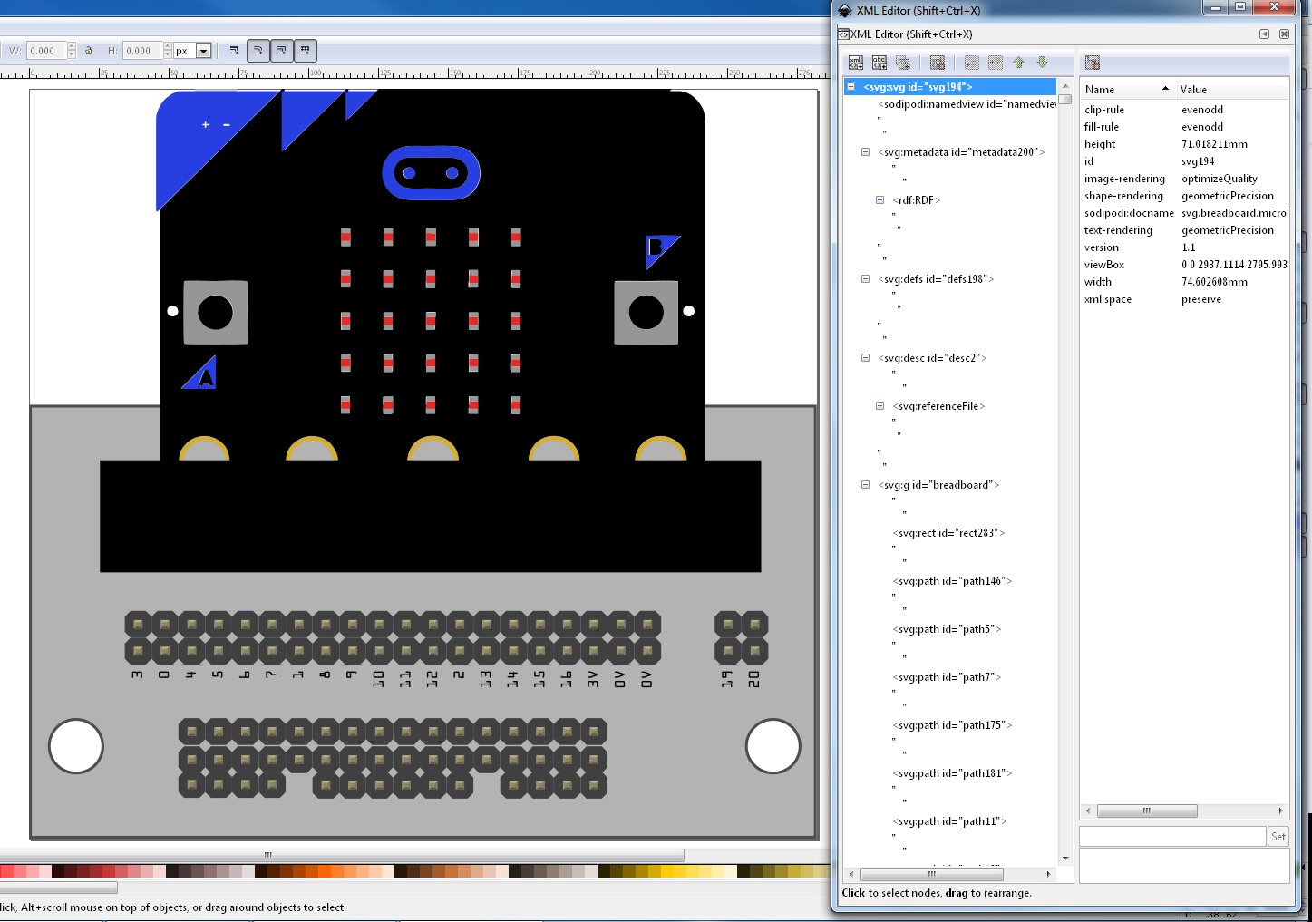
You want to edit the svg.breadboard.microbit-breakout_1_breadboard.svg file with Inkscape and make your changes, then save it and copy svg.breadboard.microbit-breakout_1_breadboard.svg to svg.icon.microbit-breakout_1_icon.svg to make the icon the same as breadboard and rezip the five files in to the fzpz file for the part.
Easy enough to do. I have replaced the first one with a _2 model with the changes. It is perhaps more complex than you expect, you need to change the _1 in all the file names to _2, then edit the fzp file and change the moduleId and reference file from _1 to _2, change the variant to 2 and change all the image file names to _2. The new part needs different fzp and svg file names, a different moduleId and variant number to co exist with the original one. If you load both at the same time Inspector should let you select which variant you want and swap one for the other (as they are identical except for color)
I use 7zip on Windows, I’d guess the .fzpz may be confusing iZip. 7zip doesn’t care what the extension is, it appears to look at the file contents to see if it is a zip file or not.
Hello Peter,
I am new to Fritzing; I’m starting to use it for Code Club projects with the BBC microbit.
I tried using your Microbit-breakout_2 breadboard part, and it works!
But I would like to ask for some changes (in the future I will try and make them myself but I got stuck because the documentation doesn’t match the tool!).
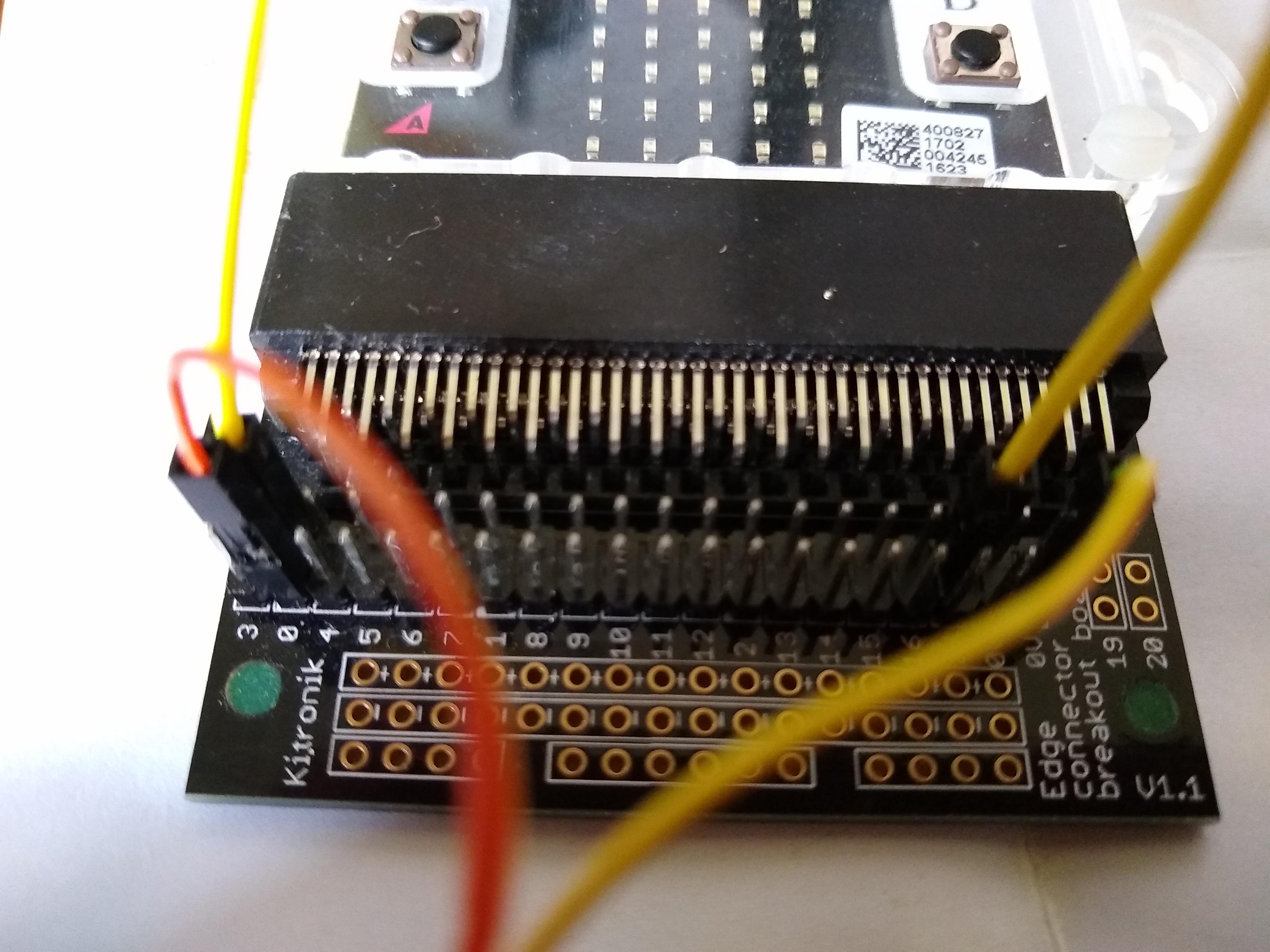
The breakout board (sold by Kitronik in the UK) has the upper and lower rows of pins connected together on the board. Could you add connection points on the upper row please, so that each pin on the lower ow is connected to the pin above it on the upper row? To clarify I have attached a photo of an actual board - in this photo the orange and yellow wires on the left) are connected on the board itself.
That part it too much of a mess to fix, at least with Inkscape. All the parts coming out of FZ lately have double quotes between objects in INK’s XML editor, and with so many objects you can’t fix it unless you directly XML text code it.
@Old_Grey Could you expand a bit on the double quotes problem? I have not noticed anything with the paths I have used. Is this with parts created with the parts editor? Do you have a sample around I could look at?
I’ve noticed double quotes turning up lately that weren’t there before.
You kind-of have to delete them all 1st because it scrolls for ages with so many objects, ie, not many fit in the XML edit box.
I know we had the problem of FZ adding lots of groups in the old days, ie, you would make a part with 3 groups for PCB view, but after you added it to FZ and exported it again, every group would be buried 20 groups deep.
Still using 0.8.3.
Depends on which documentation you are reading. The official docs are somewhat out of date but both my and Old_Grey’s tutorials describe the current version. They are in the tutorials guides section of the forums. That said, this is not the part to use as you first part, as it needs a bunch of hand editing to make work.
Yes, that is simple. I didn’t have the board and there (as I recall) was no indication where the top row connected if anywhere so I left it out.
I’m guessing that you are referring to wires in breadboard, in which case I don’t know of a way to make the text the top layer (I don’t thing there is one but could be wrong.) The wires are the top layer although you could try selecting a wire and then try moving its layer back (I don’t have Fritzing on this machine to try it.) The numbers could be added to the top row of connectors which may not match the real board (which is normally what parts should do.) and then if all the wires are routed towards the bottom the top pin label should be visible. As well if you hover over the pin in Fritznig it should come up with the description of the pin, but that won’t help if you are printing a copy for documentation. I’ll make the requested changes to the part and can add the bottom row of three connectors if you tell me what they do. It may take me some time to upload the new part though.
I think this is because there is a type=preserve (which I think Illustrator wants) in the svg. Lxml (used by both Inkscape and the parts check script) is one of the only programs that obeys the type=preserve (that is from memory, so search for preserve it may not be type …) remove that in the svg and things will display normally again (but illustrator may be unhappy with the result .) As well this part is strange, in that it has both copper layers to allow traces in a part and thus needs to be hand edited to change. There are copper traces from the headers to the 80pin connector in pcb on this part which is why it would be a poor place to start trying to make parts .
Yay. I can’t delete the preserve line in INK, but I could in Wordpad, and now it’s clean.
EDIT
The connector terminals are there but have to be assigned, but that crashes my FZ so the svg probably needs work beyond my level - I’m getting a copper in copper error for the BB view -.

 . I’ve made most of the requested changes, the pins are a problem though. Fritzing changes the active pin area to red, and that can’t be changed (as you will see from the svg the pins are really gold).
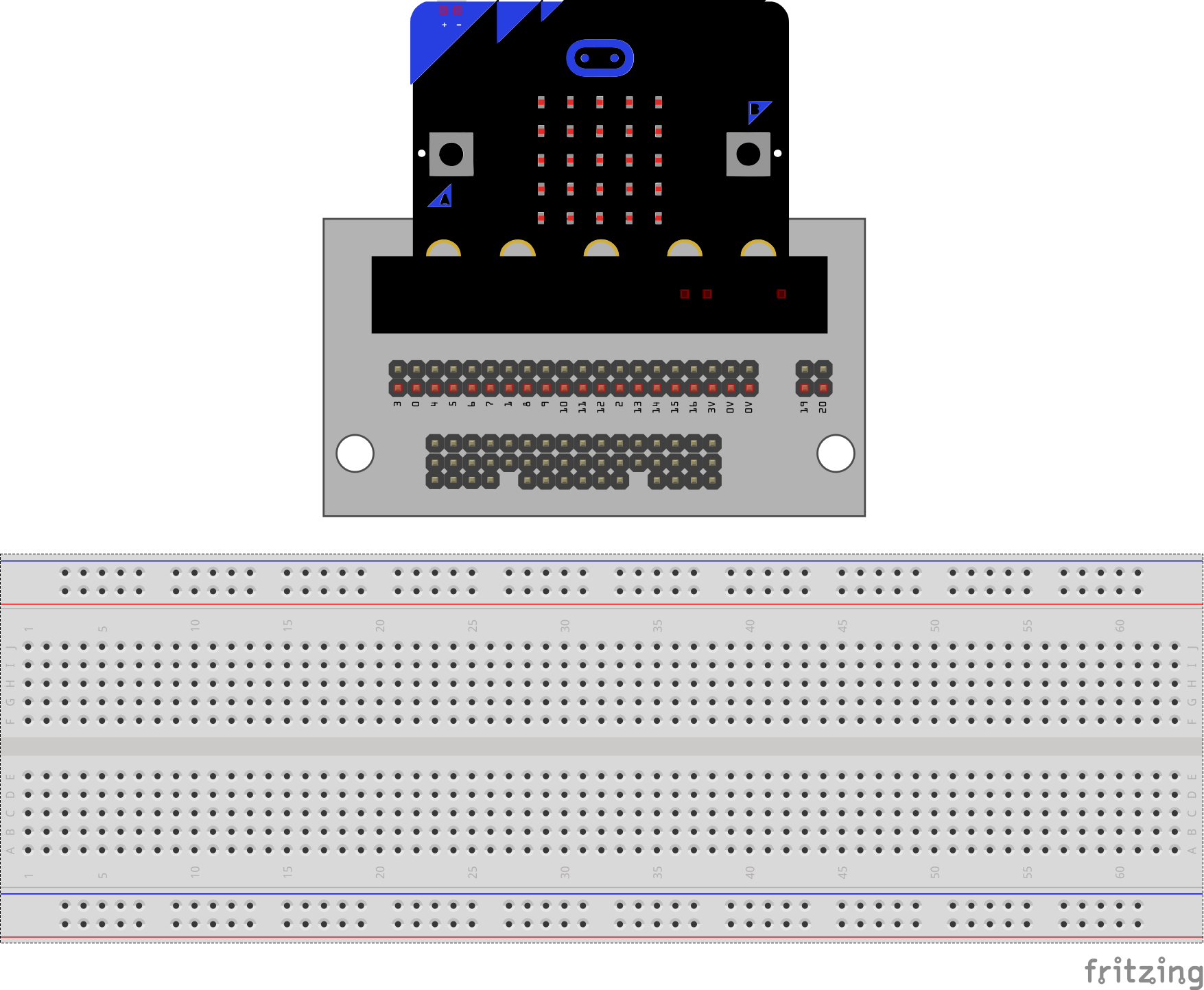
 Next time I use my Windows7 Virtual Machine.