I hoped to avoid repeating much of previous posts but, I’ve gotten long-winded… you may need a coffee break
Been using Fritzing for a couple of years and have made many PCB’s (mostly on my CNC mill but, some via Chemicals - usually as a demo to others on how to do it).
I’ve made a dozen parts for my Fritzing Parts bin - Parts that meet my preferences for ‘this & that’
I’ve gotten fairly proficient at using Inkscape but, I don’t like that App and always run into some issue.
I played with this for about a year (on once-in-awhile basis) and have posted a couple of parts/pcb/etc and this post is not about making Parts/PCB’s - it’s about the Drawing tools.
User experience/needs differ widely such that, this is about ‘Me’ and ‘My’ needs/preferences. If what I post/posted helps others, great.
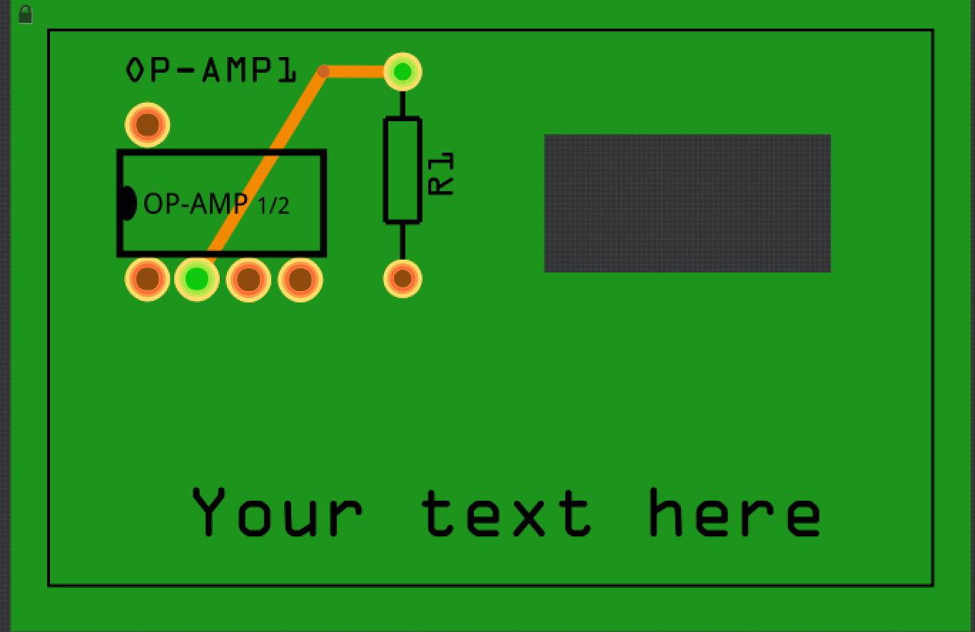
Thus, I setup a baseline PCB and Part to work on and test with these App’s:
• Inkscape
• OpenOffice (Drawing)
• EZ Draw
• Gravit
• Boxy
• FreeCAD
Goal(s):
• To eliminate need to edit the XML
• Provides for Layers/ID naming
• Provides for re-arranging layers (order, sub-layers)
• Industry Consistent drawing tools (Fill, Units,…etc)
• A clean/useful user GUI
• That is uncluttered
• Does not require additional panels to do the job
• Retains Recent-File list and/or Tab’s
• Facilitates quick editing & tweaking
• Exports SVG’s that plays well with Fritzing for:
• PCB
• Loads the: Shape, Cutouts, Silkscreen
• Exports Gerbers properly
• Parts
• Editing / Creating from existing “Antenna” part
(I use that for my baseline part starting point as it is clean with minimal need to delete Connector/Pins… etc)
• Exports Gerber’s from Fritzing with details needed in CopperCam (for CNC/Gcode)
• Runs/plays well with Mac
• That will replace need for additional App’s
• Be useful to others (though, that’s last on my list)
• Avoids the issues with Open_Source and has responsive user forum, tutorials and manual
Summary:
The Bad -
With the exception of Gravit (will talk about that at end), all Apps required some fussing, work-arounds and XML editing.
The worst is FreeCAD - Excellent for CAD/other but not for SVG’s.
Next worse is Inkscape.
An improvement on the GUI is EZdraw. Has a layer panel but XML needs editing to delete the word “layer_” from the ID’s.
OpenOffice’s Drawing does great but, some XML edit may be needed depending on the PCB and/or Part.
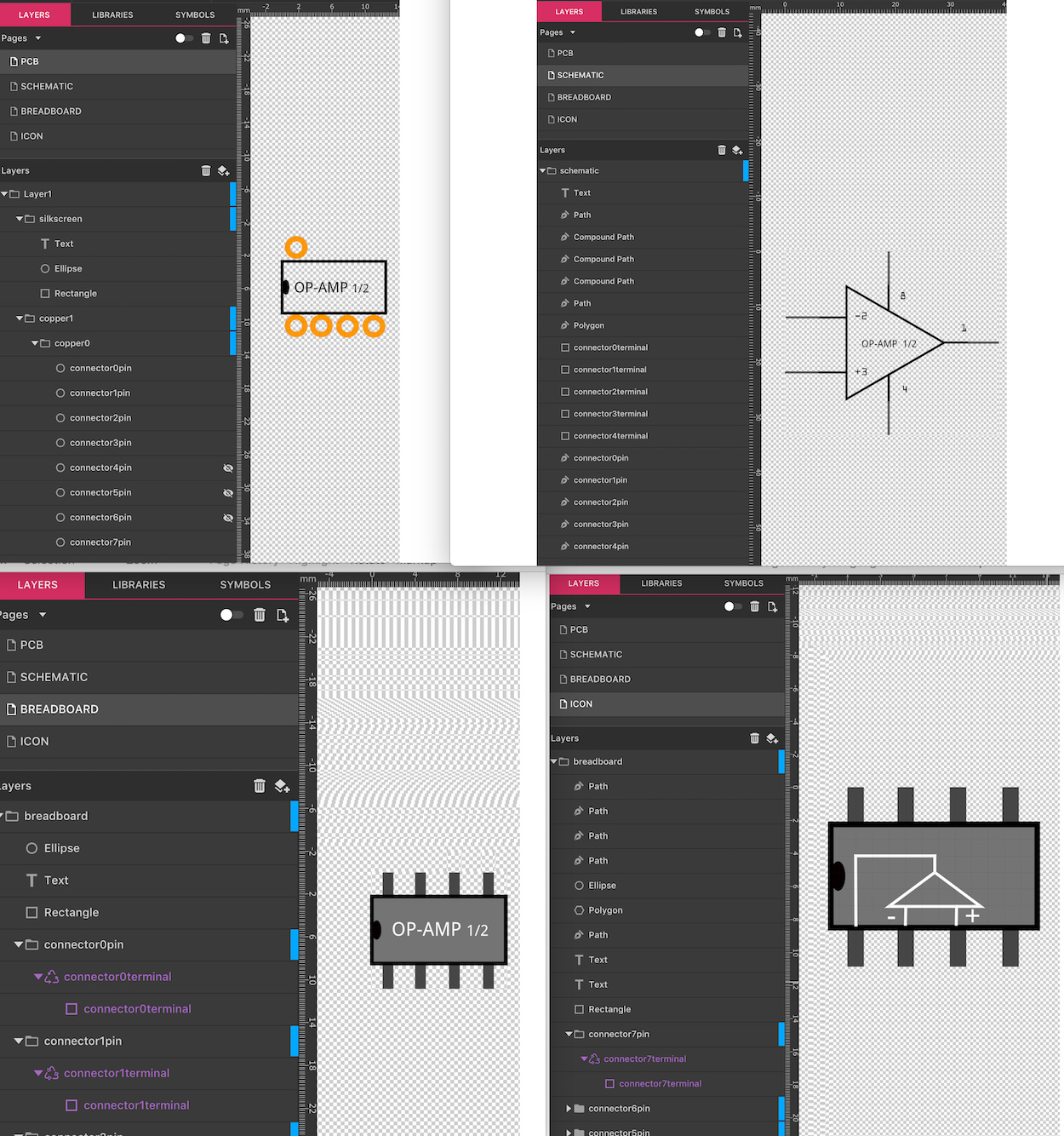
Boxy is a useful App and has an XML edit Tab at window bottom. Some-learning is needed to understand how and what Tools to use to get the XML labels/ID’s correct. Otherwise it’s better than Inkscape.
The Good - actually, the best
Gravit Designer meets all and More than I expected. The current Release has one slight hiccup (not a Bug);
It includes some text in the XML that needs deleting for Fritzing Parts to work.
This is on their list of things to change. Thus, a quick edit to simply delete the text is needed. And, it’s temporary until next release (I hope)
So, I continue to ‘Praise’ Gravit with these few words:
• Nice Layer panel enabling Drag & Drop and Re-arranging/sub-layering
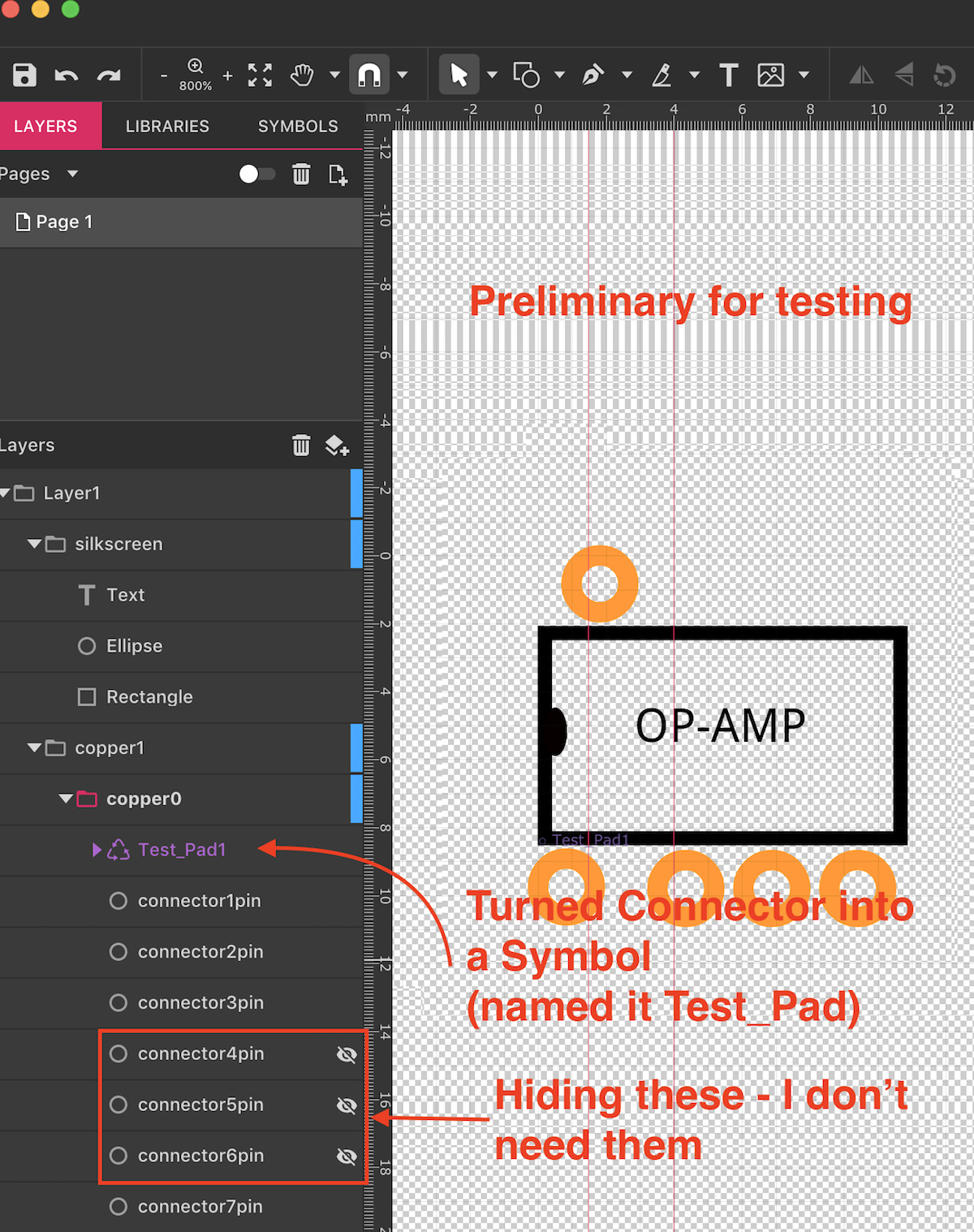
• A ’Symbols’ panel/feature
• Example of usage:
• Say you create a contact Pad for a 28 pin DIP
• Right-click, Make it Symbol
• Now, can Drag & Drop multiples from Symbol Panel/Tab
It’s like a Copy/Paste or Duplicate
• Various ways of Exporting
etc… etc… etc…
Concluding:
I’ve spent only an hour with Gravit but have discovered the usual things needed to know for accomplishing PCB/Parts - a few took a bit of head-scratching so, here are a couple of Tip’s for those interested in Gravit…
• Similar need-for-settings of things like Transparency, Stroke… etc (as done in Inkscape) are also needed but, syntax (what they’re called can be different)
• Example: “Stroke” in Inkscape is called “Borders” in Gravit (for things like rectangles). Size is in ‘px’ for drawings done in px and it’s in ’pt’ for drawings in other units (mm, inch…)
• Scaling can be done for Exported files or can simply set the Keep Ratio icon then multiply the Size value by 1.25 to make Fritzing happy. FYI 90dpi/72dpi = 1.25
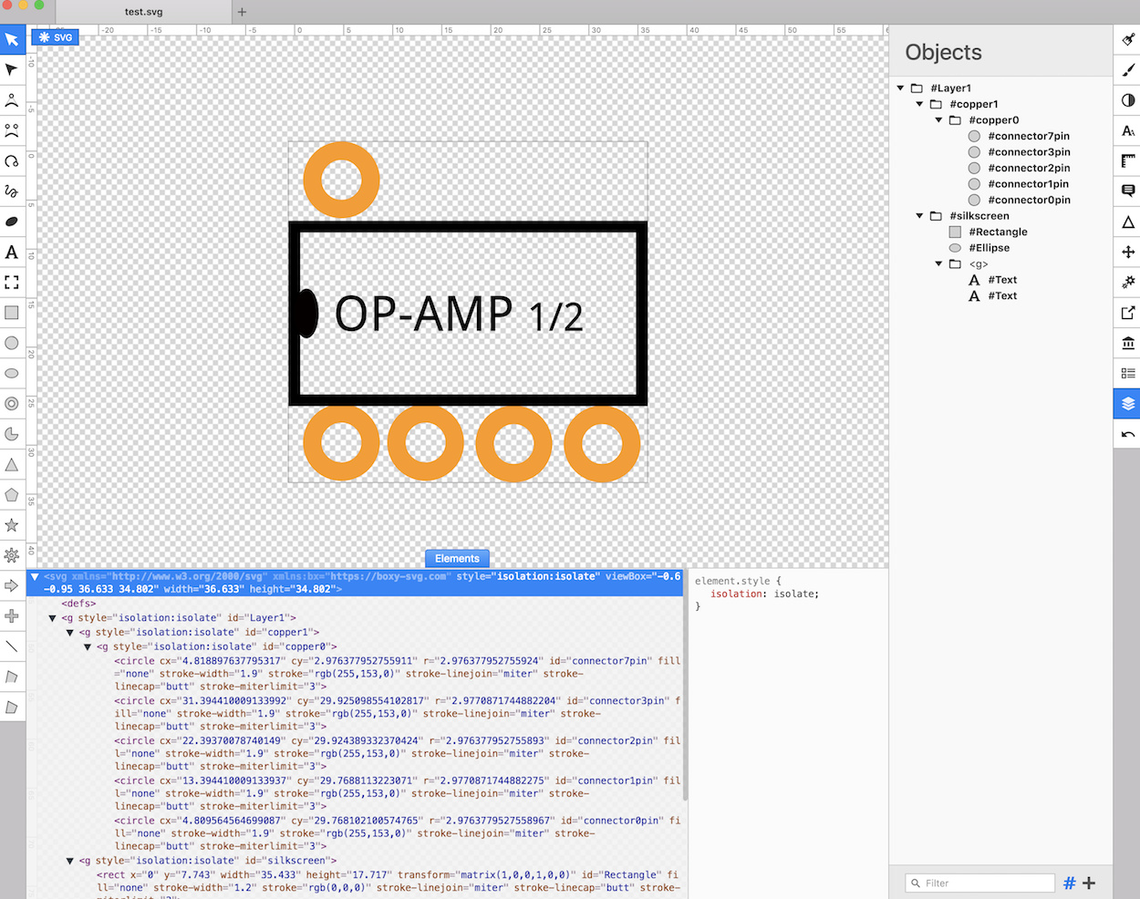
Below is clipped-screenshot of Gravit - take note of the default GUI layout
- It took only a few moments to setup the Layers and connetcor pin’s. Take 10x longer in Inkscape!
There isn’t an Editor for the XML. For the temporary need to delete the previously mentioned Text or Other elements (such as Transform or others, if needed), I use BBedit.
BBedit and it’s Free version, TextWrangler are very useful:
How I use it:
• Create the Part and export the SVG. Open the SVG with BBedit/TextWrangler
• The text will not be formatted so, on Menubar:
Markup>Utilities>Format…
Set to Strict hierarchical
Click Format
• Now, for the short-term need to delete text:
Like in any other editor, Highlight the text to delete,
Search>Replace All
Bingo, save the file.
Leaving BBedit/Wrangler open to the file just edited will allow it’s updating to a newly exported revised file.
It will show up as un-formatted so, simply repeat the format and delete/edit…
Also, BBedit/Wrangler has a ‘Preview’ window to see the graphic!
Screenshots below: Clipped-view Gravit GUI and XML in BBEdit

 All contents are as natively created in Gravit.