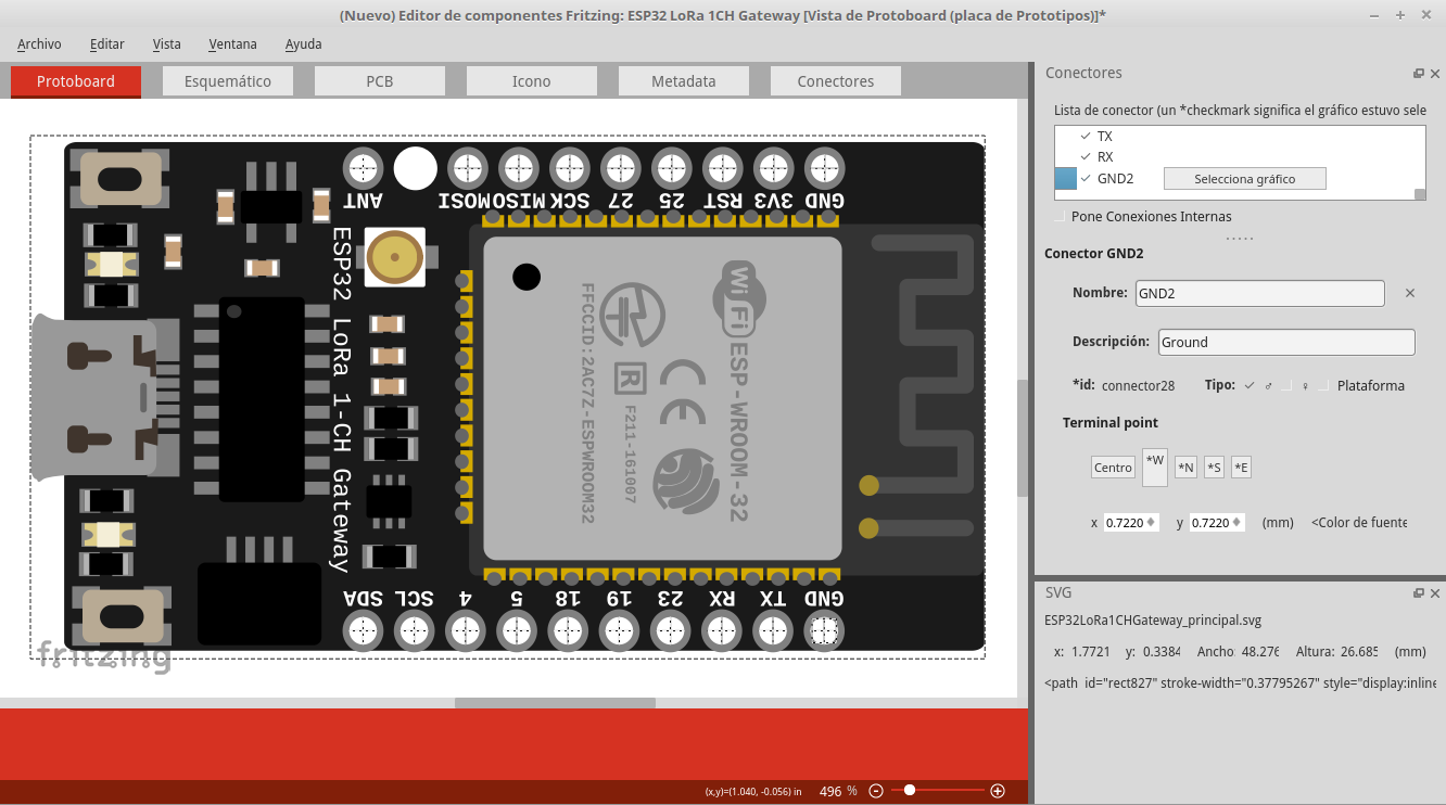
Hola gente, miren que luego de intentar lo del ventilador ahora tengo un nuevo reto y es crear una placa completa hasta el momento todo iba bien con la tarjeta que por cierto es una ESP32 de LoRa de un canal para gateway que pueden encontrar info de ella por aquí en Sparkfun.
Siguiendo con el tema, me sale un error al momento de exportar la tarjeta en la parte de PCB siento que ya segui bien al pie de la letra el tutorial de configuración de PCB asi que no estoy realmente segura de donde este mi error con la pieza.
Aqui dejo el .fzpz tal y como le tengo trabajando ahorita para salir con el esquema para el taller que necesito para crear una imagen de respaldo para los estudiantes por si es util : ESP32 LoRa 1Chanel Gateway .fzpz (111,6 KB)
Ademas de los editables que tengo armados para ello:
Hay una serie de problemas y ahora es tarde, probablemente será mañana antes de que tenga una versión fija.
Peter
Traducido por traductor de google:
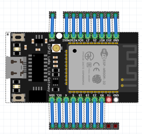
OK, here is a fixed part and some of what was wrong in yours. Mostly you are missing some pins (ground in breadboard and one pin entirely missing in pcb). As well you are missing terminalIds in schematic. In breadboard the missing ground pin is not red like the active TX connector next to it. That is because it doesn’t have a terminal defined in the svg:
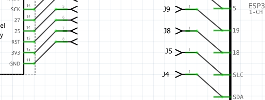
In schematic the lack of terminal IDs causes the wire to connect in the middle of the pin which isn’t what you want. My part on the left has terminalIds to terminate the wire in the correct place:
You will also note that I made the schematic image much smaller to save space in a crowded schematic. If that doesn’t suit you, you can just edit the svg to make the schematic larger again. I also renumber the pins in order from SDA which is connector0 (because the pins should start at 0). This part is a new part so yo can load it along side your original part to see what I changed. If you have questions feel free to ask. Here is the test sketch that I used to verify my part (along with the parts checking script) where the attached images came from.:
Muchas gracias tus observaciones me han ayudado en especial en la sección del equematico ya solucione lo de los pines.
Acá como ha quedado:
pero con el pin de tierra que me indicas que no esta conectado es mas que todo porque no puedo o mas bien no me acepta el archivo del pcb para poder agregar ese pin me da un error de algo con el cobre y no entiendo donde esta la modificacion que debo realizar.
Ya hice del svg lo guarde como svg plano pero no se si quizas la capa de cobre deberia ir en una capa diferente a la guia de en negro de la placa.
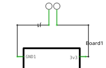
It is probably easiest if you upload the svg here (rename the .svg to .fzp first, the forum often has trouble uploading svgs). I assume that you are doing this in parts editor? I rarely use it and just edit the underlying svg files, but given the file I can likely fix it. I did make extensive changes to your pcb layout as it was for the chip it was cloned from and as noted has one less pin than required, was too narrow and lacked the silkscreen showing the edges of the board. You could just unzip my part and try loading the pcb svg from there, it should work fine for your original part. Note I also bused the two grounds together in the fzp file as they should be. In any view of my part if you click on one ground both of them will light up yellow to indicate they are common.
super gracias hoy si la pieza me trabajo, entendi varios detalles que no me habia percatado con el diseño de piezas en fritzing. Sos lo maximo @vanepp. En serio gracias, hay te puse en la autoria de la pieza.