Hi,
I just started a new project. It should be an auto-controlled tractor with Mosfet.
Here is more about it. It is pasted here from the code in Fritzing.
// Auto-controlled tractor that can avoid obstacles, the servo is controlled by LDR’s.
// We can start the DC motor with the toggle switch. The DC motor drive the two back wheels.
// The tractor can go just forward.
// We control DC motor with a MOSFET.
// We can set the speed of DC motor with potentiometer.
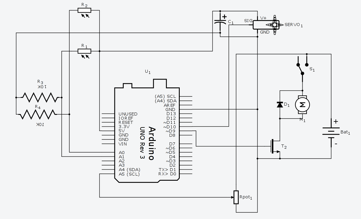
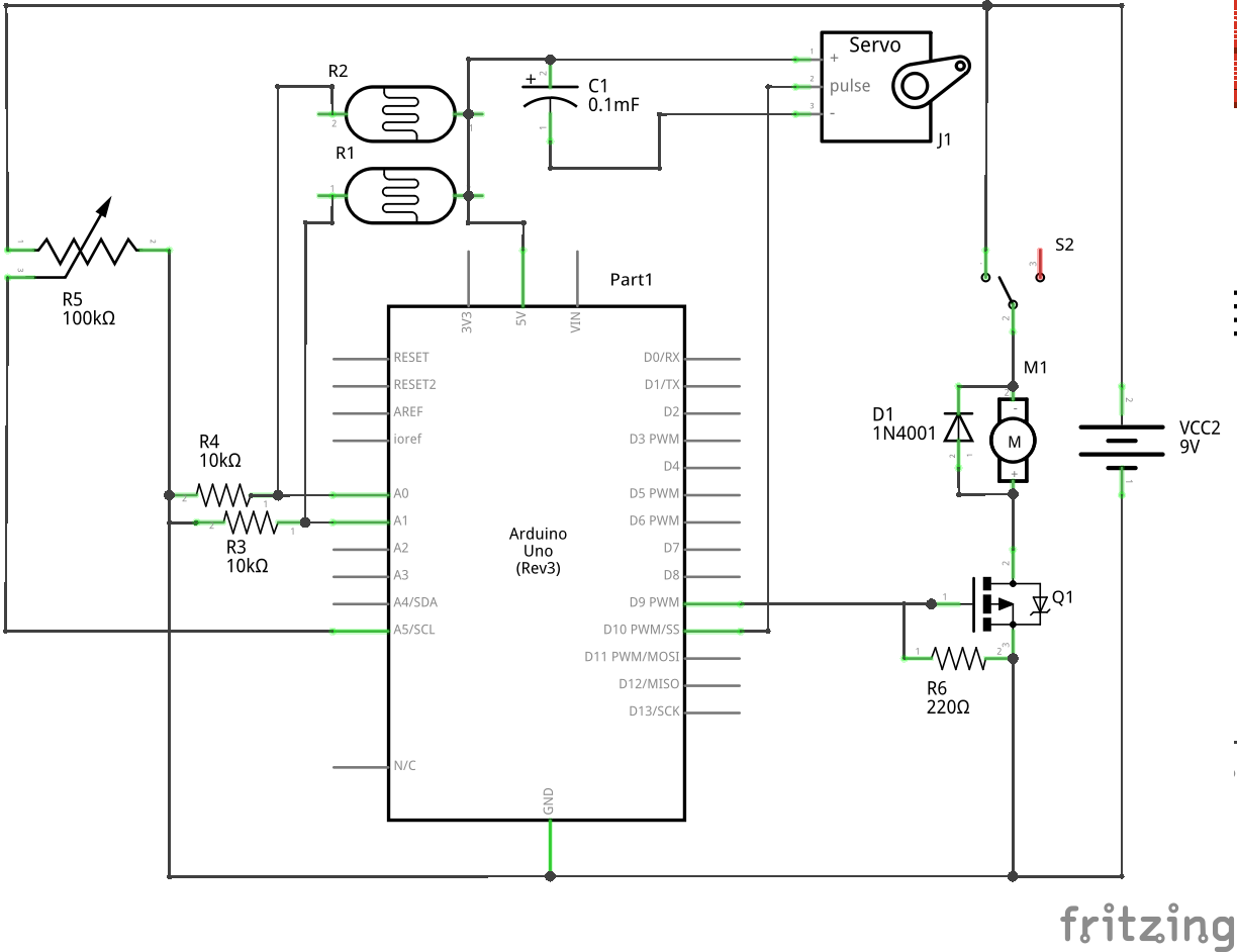
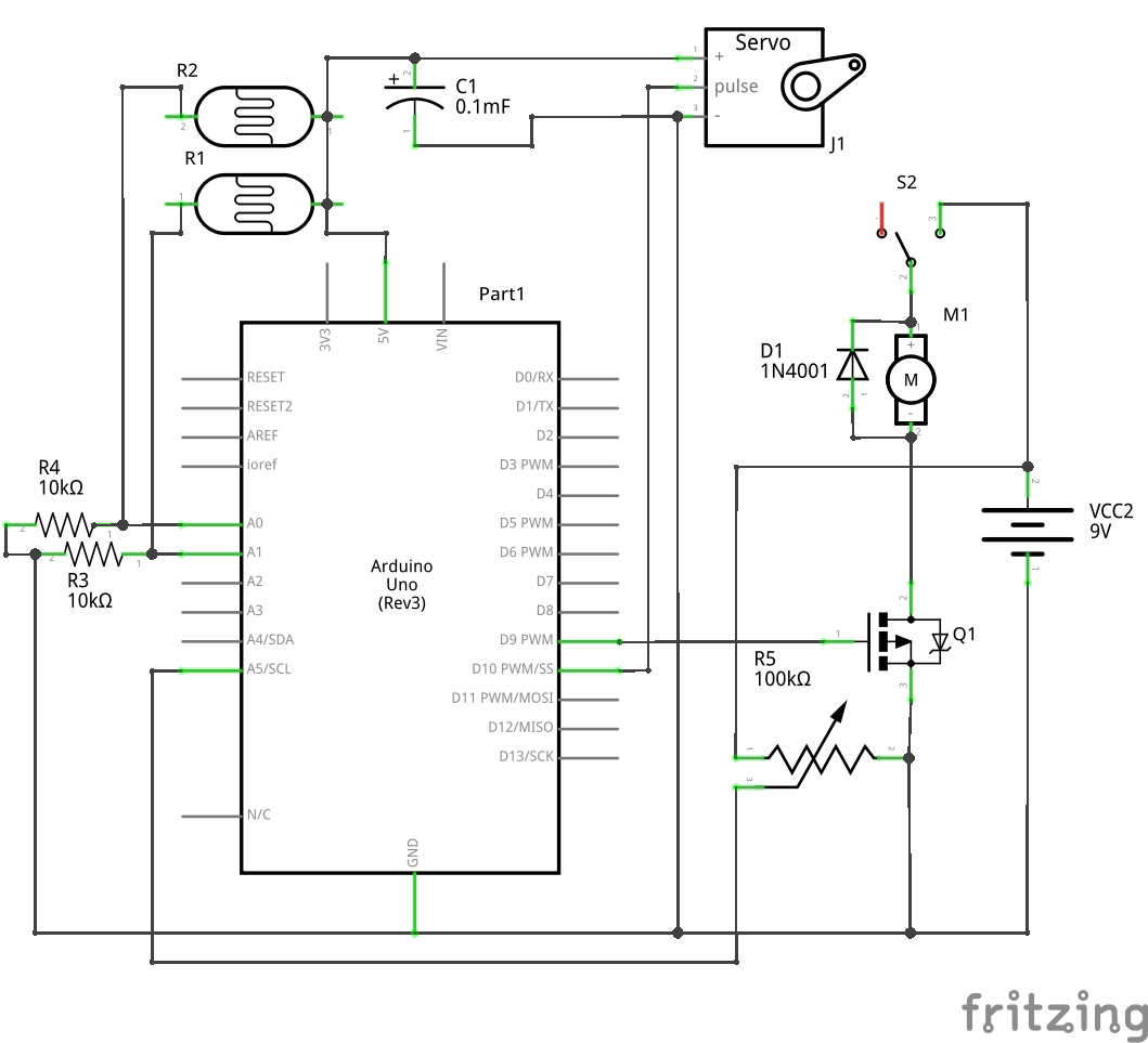
I made the circuit so far by using a few circuits from here and from there.
Here is the image of the circuit:
If it works then its good or at least good enough. If the motor is 9v and battery life is OK, then you shouldn’t need another battery. You do want to be careful with the wiring, the ground wire to the motor should go to the mosfet and a separate ground wire from the battery to the arduino (as the motor will induce noise in to the grounds which may affect your analog measurements.
I should have asked earlier, but I assume the 9V battery is also powering the arduino? If so in the real world you want to run a separate wire from the battery ground to the arduino ground and a second (wire from the battery ground to the Motor and Servo (both of which have motors). The current spikes from the inductance and pwm switching of the motors can cause voltage drops (due to wire resistance) in the ground circuit. That in turn will change the level of the analog voltage a bit (which may or may not matter in this case). As always the acid test is to wire it up and try it and see if it works . If it works sometimes but not others then the grounds are a thing to look at (but its easiest to wire it correctly the first time ). Assuming you are reading analog voltages I believe you also need to connect the arduino 5V wire to the aref pin on the arduino to set the analog reference voltage (I didn’t notice that wasn’t done the first time).
Ah, then a single wire from the ground on the arduino battery to the ground on the motor battery (and put the servo ground wire on the same ground as the motor) will do the trick. The schematic will look the same as the connectivity is identical, its just arrangement in the real world that is important. Depending how much current the drive motor takes and how low a voltage it will take while still giving you enough torque to drive your chassis, you may be happier with a pack of AA batteries or
NIMH or LIPO (fire risk though, I usually avoid them) rechargable batteries. The 9 volt batteries are low amp hours and the motor will probably drain them fairly quickly. I’d try a four pack (6V) of AAs and see how the motor runs with them
While I don’t know anything about the simulation site, the error message seems to indicate the simulation can’t yet handle something you are doing (perhaps the analog stuff which I assume is reading the ldrs?). I do notice that aref is still disconnected which may disable analog reading (as it will in real life, without a reference voltage I don’t think the a/d will work). You might try connecting 5 volts to aref and see if that makes it happier.
Then it may be that the simulator can’t simulate the analog portions (I expect that would be quite difficult to arrange, but I don’t know). As I said based on the error message there seems to be a limitation in the simulator. Its documentation may give you more information, or if they have forums like this one ask there.
I’m not sure you are doing something wrong as much as running in to a limitation of the simulator. Your circuit looks fine, I suspect the problem is trying to simulate the analog portions of the code. The simulator doesn’t have a way (without a lot of complex additions) to know what the value of the analog voltages on the pot and the ldrs are is I suspect the problem . For that you may have to try it with actual hardware, simulation can only take you so far
 . If it works sometimes but not others then the grounds are a thing to look at (but its easiest to wire it correctly the first time