Adafruit Permaproto causes lag

Steps I took that resulted in the problem:

Import Adafruit Fritzing Library
https://blog.adafruit.com/2012/08/27/how-to-install-and-use-the-adafruit-fritzing-library/
Place the permaproto half size (any other should do as well) board and add a few components
editing will become very slow and laggy

What I expected should have happened instead:

should be smooth and responsive

My version of Fritzing and my operating system:

0.9.3, Windows 10

Please also attach any files that help explaining this problem

Happened to me when there are too many detailed parts at the same time and you zoom out. Seems to be a problem related to program perfomance which can’t be solved right now since there isn’t maintenance from devs.

Try turning off the grid feature. If it is set to a low value it can cause massive lag. If turning it off helps but you want to use it then set it to as large of a value as you can use.

1 Like

I can confirm that there is a significant reduction in program performance when any size Adafruit Perma-Proto PCB is used added to the BB window. I Also reproduced this lag with a similar setup as you are working with (Win-10 & Fritz-9.2b).
KC

Would you please post an example sketch which shows the slow response time? I tried with an older (2017 vintage) adafruit part and don’t see an unacceptable reduction in response on 9.3.b on Win7 pro, but there may be a later version of the part that reacts worse (or I may have used the wrong part :slight_smile: ).

Peter

I noticed the same thing today on Ubuntu. It wasn’t a problem when I tried them 1-2 year ago. As soon as I started trying to place any parts on the board, each hole would flicker blue really fast as the parts passed over it. I’ll try my older Adafruit library to compare.

Interesting, because I’m not seeing this even with the latest adafruit version on 9.3b and win7 (or I’m using the wrong parts). Check your view->set grid size is set to the default .1 in (finer grids are known to cause this problem) if you haven’t already. If I could get it to reproduce I’d look at the coding of the part as being the likely performance hit (but as noted I can’t reproduce this so far).

Peter

@Knochi
Well, This reply is many moons later but I figured out that the cause of the lag on my MacOS machine was a super complicated background layer in the Icon and Breadboard SVGs. I have removed the overly complicated layer with a simplified one and “generic-ized” some of the common Adafruit Perma Proto boards.

Generic PermaProto Mint Tin Size.fzpz (27.1 KB)
Generic PermaProto Small Mint.fzpz (23.4 KB)
Generic PermaProto Quarter-sized Board.fzpz (17.3 KB)
Generic PermaProto Half-sized Board.fzpz (24.7 KB)
Generic PermaProto Full-sized Board.fzpz (41.4 KB)

:slight_smile:

1 Like

Even better – why not just suppress Schematic and PCB view?

Generic PermaProto Full-sized Board-fixed.fzpz (25.1 KB)
Generic PermaProto Half-sized Board-fixed.fzpz (14.7 KB)

Just dump down the file size!

Another thing, missing breadboard layerID in SVG, and scale is in PX

:smiley:

https://github.com/adafruit/Fritzing-Library/pull/195_spoiler

Temporarily closed

Note that the parts were originally dimensioned in PX, so the scaling may be wroong after the rescale. 0.1in headers don’t align.

(No solution :sob:) @vanepp any help?

Yep, rescale the svgs using Inkscape. You can do it a variety of ways, if you know what the original DPI was (72, 90 or 96DPI ) you can use a calculated % to do the rescale, Or you can measure the distance between 0.1in headers in the svg, then calculate the % increase or decrease needed to scale and hit the target by trial and error. I’ve done it both ways and both work. As well suppressing schematic and breadboard in this case may be overkill I think these are protoboards and breadboard and schematic may be useful (and the file size isn’t that significant.)

Peter

Why do you say suppressing schematic is an overkill? It isn’t particularly useful.

If they are proto boards as I think, people want to wire them in breadboard and route schematic (and maybe produce a pcb) so not having breadboard and schematic will likely cause complaints.

Peter

1 Like

Actually they are just the same as normal breadboards.Adafruit has another version of the PermaProto (which is a real protoboard), and those require a schematic. In this case, not very useful

I would agree schematic for the protoboard isn’t useful the parts will appear in schematic anyway. Pcb probably isn’t too useful either as the parts will all appear in pcb (and you likely don’t want the pads getting in the way) so only breadboard needs to exist (and could become a real breadboard and probably should.)

Peter

1 Like

Can you help me with the 2 boards?

I need to figure out more python and other Adafruit parts :slight_smile:

Sure I can do them. Here is the first one and what I did to it (I suspect the others need the same treatment :slight_smile: .)

PermaProto Full-rescaled.fzpz (23.8 KB)

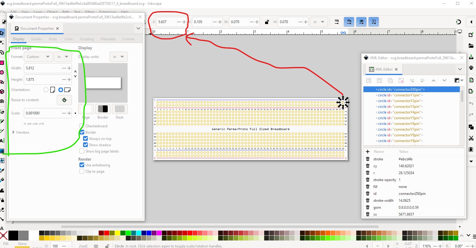
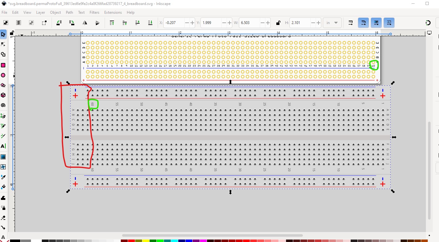
The pins are not on 0.1in boundaries so find the x coord of the left most pin which is 5.672in subtract the x coord of the right most pin from that which is 0.141in to give the current length which is 5.531in. Compare that to a standard full breadboard (or count the pins which I am to lazy to do!) which is 6.134in - 0.335in = 5.8 in (which is actually high by 0.001in but close enough for goverment work!) So divide 5.8 by 5.531 = 1.048634966552161 and multiply it by 100 to get 104.8634966552161 which is how much we need to scale up by in %.

ungroup to remove transforms

the pins are not on 0.1in boundaries so find the x coord of the left most pin which is 5.672in subtract the x coord of the right most pin from that which is 0.141in to give the current length which is 5.531in. Compare that to a standard full breadboard (or count the pins which I am to lazy to do!) which is 6.134in - 0.335in = 1.048634966552161 (which is actually high by 0.001in but close enough for goverment work!) use 5.8in rather than 5.799in to correct for that. Then multiply it by 100 to get 104.8634966552161 which is the new scale we want.

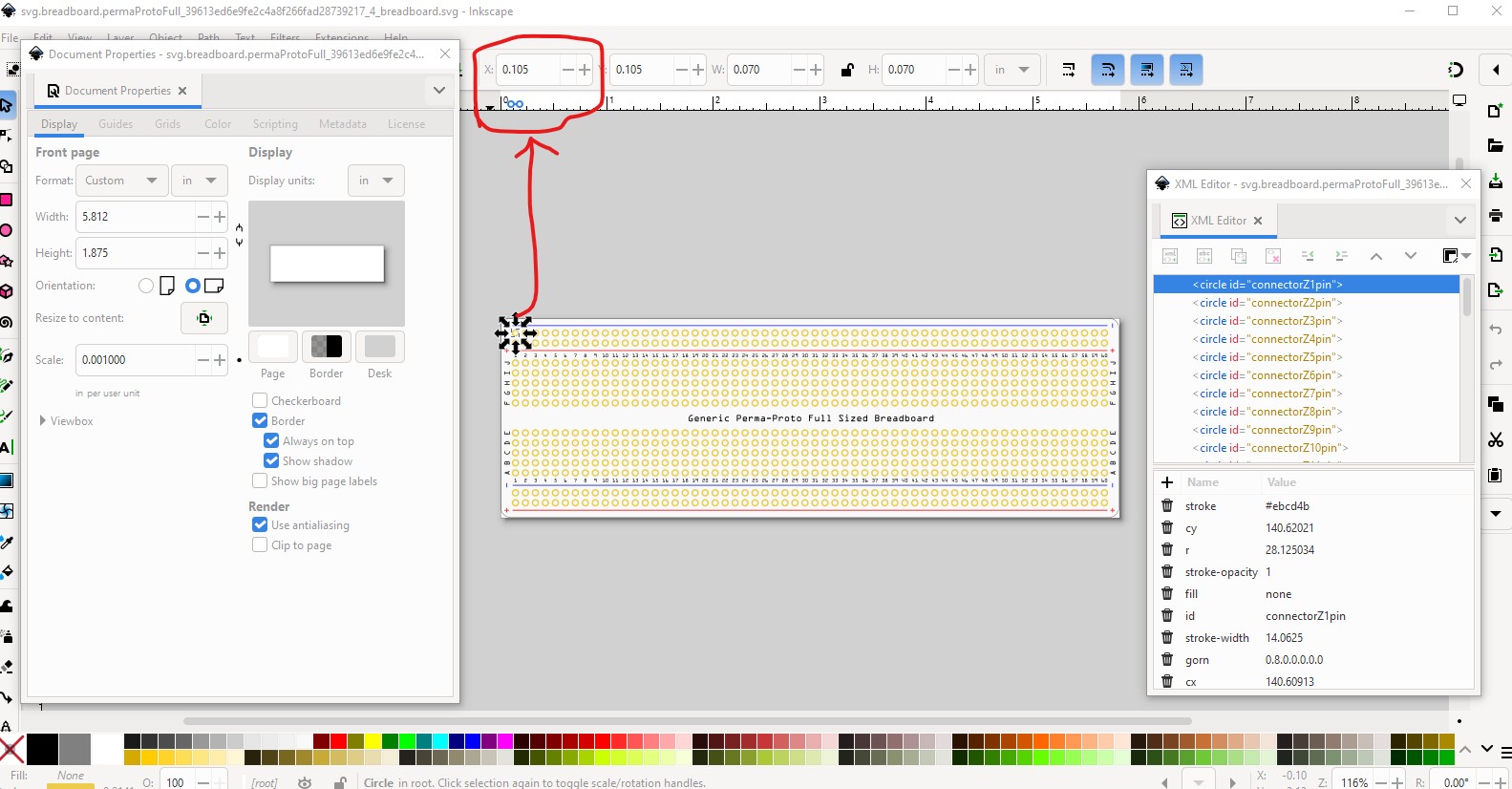
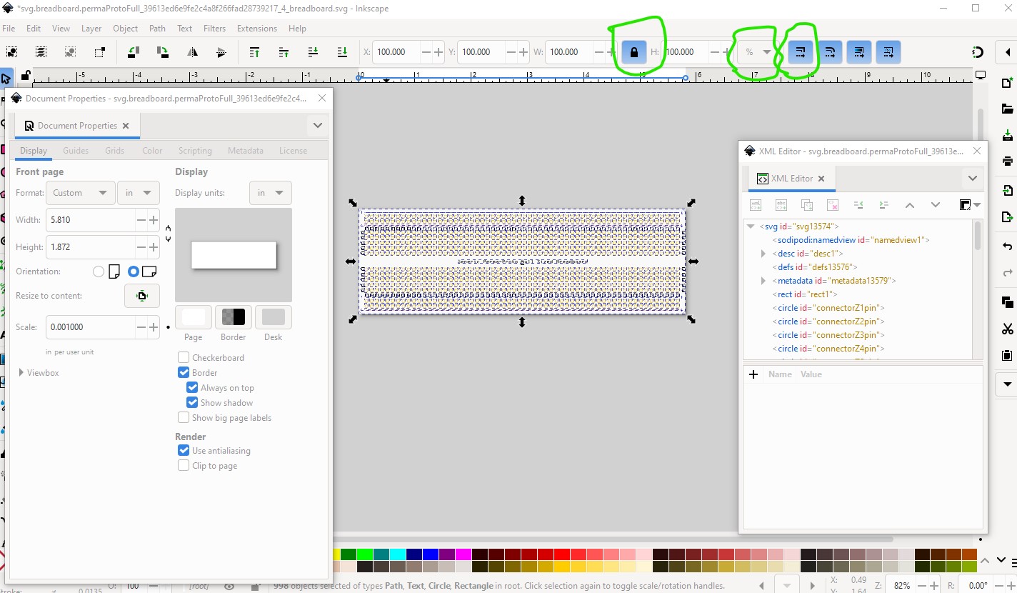
so do an Edit->select all, then a Edit->resize page to selection to fix the viewbox at 0, 0 then lock horizintal to verical (to keep the circles circles) set the dimension to % and enable scale stroke-widths to set up the rescale. Then enter 104.8634966552161 to any toolbar coord window (all currently at 100) to do the rescale. Then do Edit->select all and Edit->resize page to selection to reset the viewbox correctly. Then check the pins are now on 0.1in boundaries. Looks like we may be too high. right x = 5.911in left = 0.111in. Ah! they are lying to me. Their board is not a full breadboard (which has 64 pins) it is only 60 pins

So I do have to do this by pin count. So close the modified svg without saveing and start again.
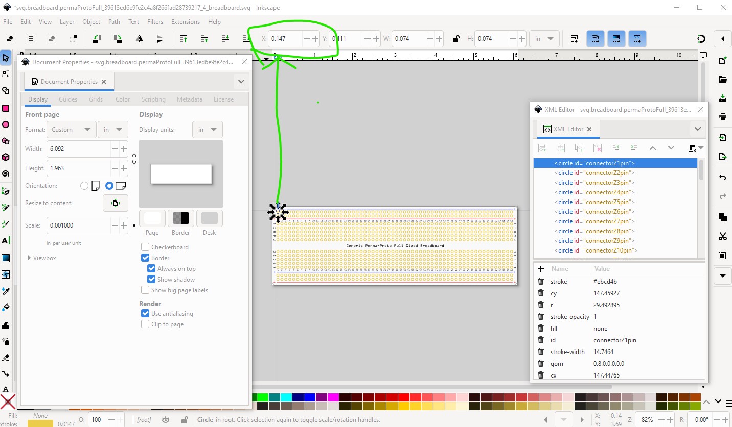
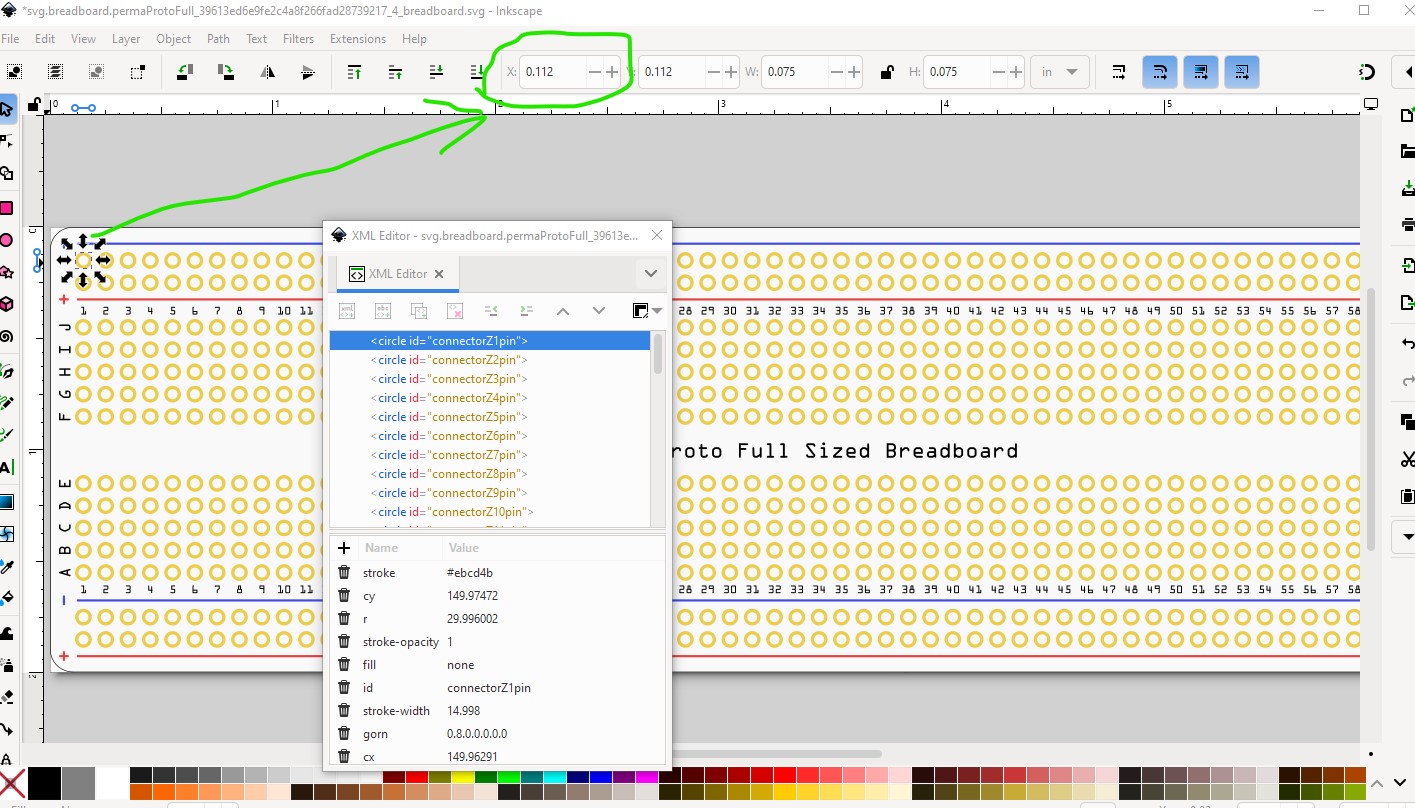
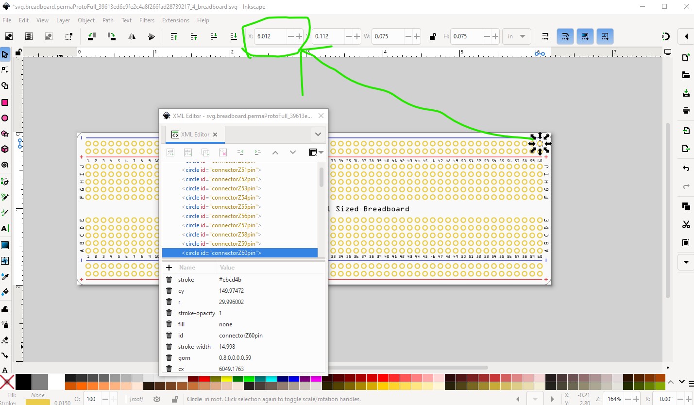
Odd I get different numbers this time. right most pin is 5.637in left most is 0.105in so length is 5.532in for 60 pins it wants to be 5.9in or a scale of 106.6522053506869% so try that and see what happens. The pins are now on 0.1in boundaries in both x and y (and all circles I hope!)

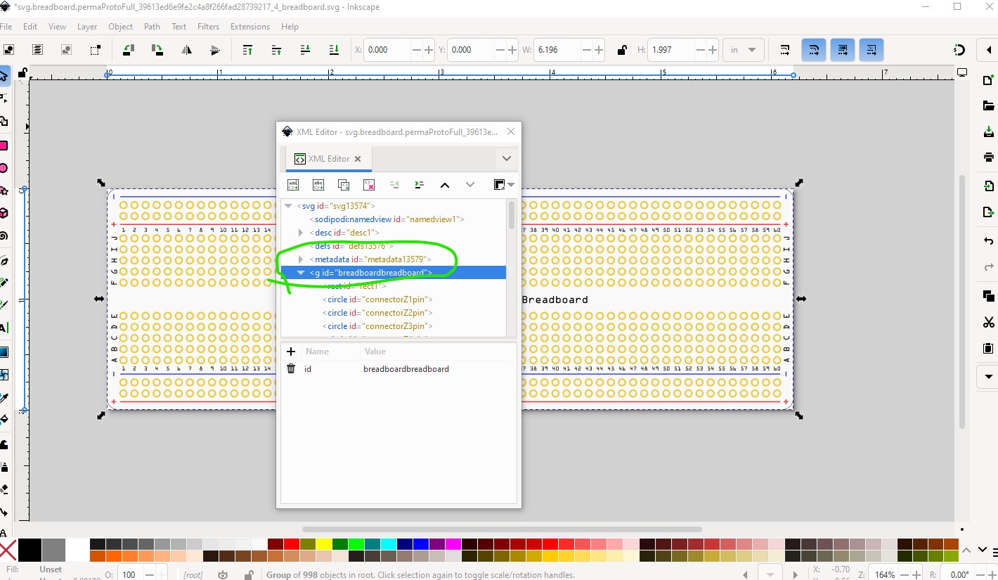
so group the svg and set the layerId to breadboardbreadboard (as this is now a breadboard in fact!)

So on to the .fzp file.

from

<module fritzingVersion="0.7.5b.07.02.6130" moduleId="permaProtoFull_39613ed6e9fe2c4a8f266fad28739217_4" referenceFile="Adafruit_Permaproto_Full_sized_Board__ae169a6a52289a88981faa0062203b34.fzp">

to

<module fritzingVersion="1.0.5" moduleId="permaProtoFull_39613ed6e9fe2c4a8f266fad28739217_4-ModuleID" referenceFile="Adafruit_Permaproto_Full_sized_Board__ae169a6a52289a88981faa0062203b34.fzp">

changing the Fritzing version and adding the breadboard prefix to the moduleId. The “-ModuleID” postfix trips the breadboard processing code on load.

from

 <author>John De Cristofaro + JR</author>

to

 <author>John De Cristofaro + JR (modified by vanepp June 2025)</author>

to admit I made changes.

from

 <properties>
  <property name="family">permaproto</property>
  <property name="variant">generic</property>
  <property name="size">full</property>
  <property name="part number"></property>
 </properties>

to

 <properties>
  <property name="family">Breadboard</property>
  <property name="variant">generic</property>
  <property name="size">Adafruit PermaProto Full</property>
  <property name="part number"></property>
 </properties>

change family to Breadboard (required to be a breadboard!)
and modify the size (as full is in use) to reflect the Adafruit part.

then do a global replace of layerId=“breadboard” to layerId=“breadboardbreadboard”

then do the same for the pins.

from

     <p svgId="connectorW2pin" layer="breadboard"/>

to

     <p svgId="connectorW2pin" layer="breadboardbreadboard"/>

to set the layerIds correctly. Then run the part through FritzingCheckPartw.py to verify it is good (lots of harmless errors FritzingCheckPartw.py doesn’t understand breadboards :slight_smile: ) I’ll do the other one tomorrow.

edit:

Here is the second one. Changes the same as the first (which probably need to be done on the rest too!)

Generic PermaProto Half-sized Board-fixed.fzpz (13.8 KB)

Peter