No problem designing my custom PCB’s and thought about making a Custom Part that is simply a Rectangle Cutout (thinking it would be simple - nope, at least not yet doable or, perhaps I lack the skill/knowledge).
However, aside from stringing holes together, it dawned on me to try using a PinHeader… and simply set the hole diameter to be the width of desired Rectangle.
Sure, the result will have radius’d ends but, easy to live! (and, a mill-bit would produce radius’d corners anyway).
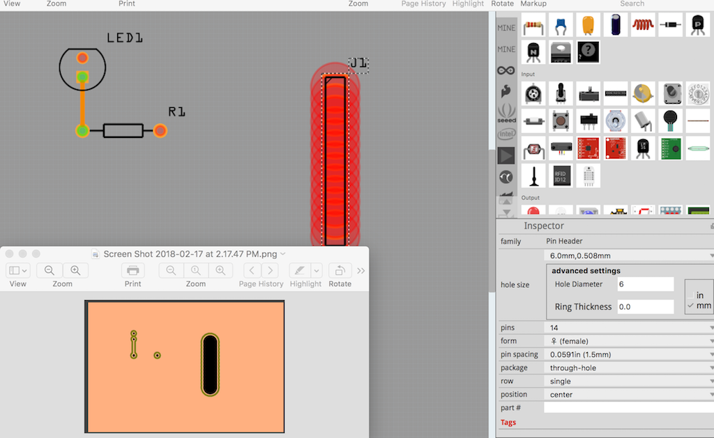
The image shows (in Red) the PinHeader and it’s parameters (pin count=14, dia=6, ring dia=0…).
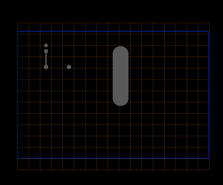
It also shows an embedded image of the result in CopperCam (I use it for Milling PCB’s).
The DRC produced no errors (needed a couple of parts (LED/Resistor) on the PCB to make it happy).
Might be a good idea (a Cheap Trick) if you need a slot or cutout…