Not a bad job overall, better than many I have seen. There are a few problems however. Breadboard is fine, mostly (the buses are wrong but that affects all views.) Schematic s where the problems start:
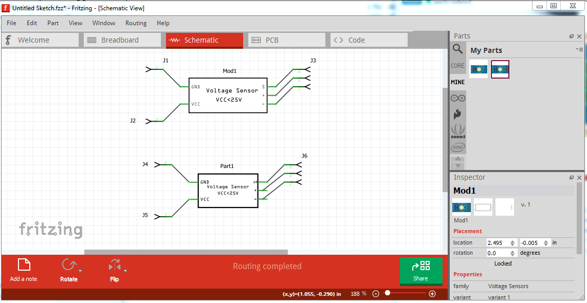
on pins 3 and 4, the terminalIds are missing or incorrect, so a wire connects to the center of the pin instead of the end. If you click on the VCC pin, the + pin lights up yellow, unfortunately the data sheet says the + pin on the connector is NC, and the GND pin does not light up the - pin on the connector pin yellow as it should. On to pcb, again there are a number of problems:

all the traces are on the top layer, because there is no copper0 layer, (just one called copper, which isn’t defined in the fzp). The two pins on the terminal block show up in pcb (where I suppressed them as not being practical in pcb.) As well your pads are not appropriate for .1 header connectors (a 0.038in hole) but rather 0.031in
from the gerber drill file.
M48
INCH
T100C0.038000
T101C0.031496
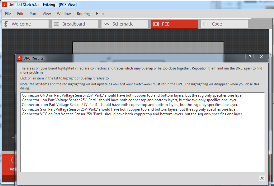
the top number here are the holes in my part at the correct 0.038in, followed by yours. As well DRC (routing->Design Rules Check) complains about the lack of a second layerId:
My improved part
Voltage-Senso-25V-improved.fzpz (9.3 KB)
and the test sketch:
test-Sketch.fzz (31.9 KB)
What I did to change your part in to mine can be found in this series:
Peter