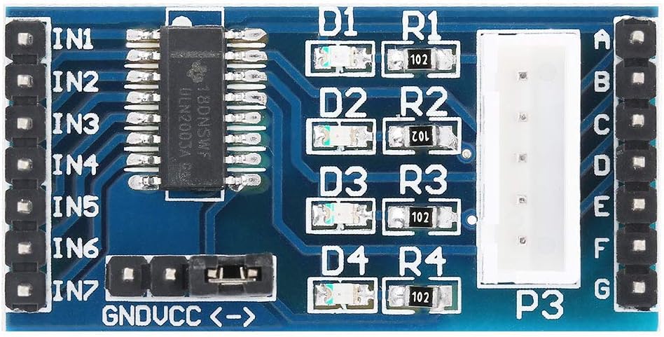
Your English is fine and perfectly understandable. You can also use your native language (I would guess Spanish) and either include the output from google translate or let us use google translate to read it. That said this part may do what you want. I had to guess at the connections since nothing online (that I could find anyway) has connection information. I made the part from this image from this site
https://www.amazon.ca/Stepper-Driver-ULN2003-28BYJ-48-Controllers/dp/B0CBRD71QK
which contains this image which details the connections and location of the parts (and gives the board dimensions in a flat jpg image.)
using this site (which has a schematic of such a board)
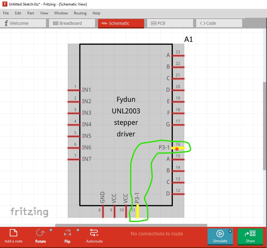
I assume that the motor is driven by IN1 to IN4 and the top pin pf P3 connects to VCC on the jumper between the ↔ pins. If this isn’t correct the part won;t work correctly, but I suspect it is correct. IN5-IN7 connect to Pins E-G on the left most header to let you use the unused pins of the uln2003 if you want to. If you click on a pin in breadboard or schematic (pcb view has been suppressed as not being useful!) and right click on a pin, all the pins connected together will light yellow like this:
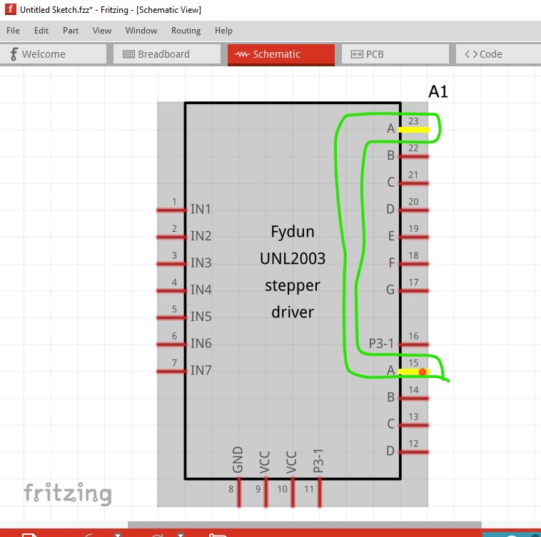
and the same for pins B-D and the two VCC pins. Here is the part that implements all of this:
Fydun_UNL2003_stepper_driver.fzpz (9.4 KB)
Peter