Hello everyone!
I’m trying to fix the incorrect pins to this part: http://fritzing.org/projects/mpu-6050-board-gy-521-acelerometro-y-giroscopio
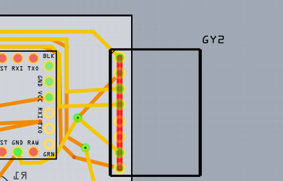
If you go to edit part>PCB tab, and click on each pin under the connectors tab, you’ll see that Pins 1-4 are correct, but pins 5-8 are all incorrect/scrambled. I know there must be a simple way to fix this, but I’ve tried for hours and I can’t seem to figure it out. If anyone has any pointer, or could help me fix this part, I would really appreciate it!
Note: I tried clicking “select graphic” next to each pin, and assigning the pins to their correct connectors, but when I go back to view my traced PCB, there is a red line through all of my connectors, so I don’t think this is correct.