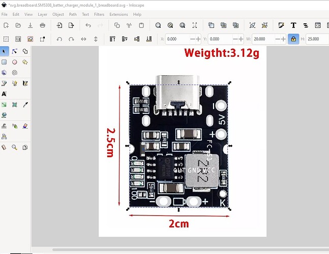
Tried that and it won’t let me save it like that. It automatically put the px back when I pressed Set.
You can’t do that in INK, you need to do it in WordPad. XML edit it
It doesn’t matter now I’ve put it in Peter’s part.
Here it is - TP4056-2.fzpz (11.6 KB)
Finally got there with your much needed help. I think I need to stop trying to design my project and start playing with Ink. That way I might get to work it a bit better. I know how to work Corel Draw better, but no matter what I do I can’t get draw to do what I want it to do and it keeps adding stuff in XML I don’t have a clue what it is. Computers will be the death of me yet. 
Use whatever vector package you like, we only use INK because it free.
I know my instructional vids will take half a day to watch, but you will save 10x as many hours than fumbling around. I don’t do any computer stuff these days without spending days watching tutorial videos because everything is complicated. Even similar programs have their own individual foibles so knowing one won’t help you with another. I would’ve spent 10hrs each on FZ, KiCad, Altium, and Eagle before I decided to go with FZ.
As Old_Grey said we use Inkscape because its free (and in my case because being free, its the most likely thing for other people to be using, so knowing its quirks is helpful). Corel Draw works fine, in many ways better than Inkscape I think. I’m working on a python script that will remove the px from font size and do a variety of other things that Inkscape does that Fritzing doesn’t like but it isn’t quite ready for release yet.
Peter
Don’t get me wrong I think Fritzing is great and look forward to your new script Peter. I agree Ink is good and even better because it’s free, but like all new programs takes a bit of getting used to. I use Corel 12 which is a good few years old now so Ink is maybe ahead of 12 in many respects. PCB design is also new to me so learning lots as I go. My main interest is brewing beer, and love tinkering, hence my current project. Many thanks to you both. You have been very helpful in pointing me in the right direction. 
As always this has been interesting and educational  , turns out the text problem is nested tspan text groups (and the incorrect fonts). I’m not sure how you got the nested tspans (most likely something Inkscape did for reasons unknown) but fritzing doesn’t like them. I’m adding a test for that and non supported fonts to my script …
Peter
Many years later, but I cobbled this together from the previous posts.
Has a nice breadboard, schematic, and pcb view
TP4056 Charger.fzp (4.0 KB)
Many thanks. I’m sure it will be useful…
Bob
Hello, has anyone worked with the Sm5308 module?
A google search of the form “fritzing part Sm5308 module” doesn’t turn up any existing parts. To make one we would need the web site which has the physical dimensions and connector information for the module you want (there appear to be a variety of them in a search for Sm5308 module.)
Peter
oh… seen this part too lately,
I’ve used this charger module for some of my projects
which I only used raw footprint pads for the design:joy:![]()
not a part but sufficient in my way
Nice and thanks for the work, so It’s usable in future
I tried to find information about this charger module (SM5308 m040) but the only thing I found are measures of the sides of the module, I could not find its datasheet either.
in this link I found the measurements
Hi, could you please provide me with the dimensions of the module you worked with?
Please
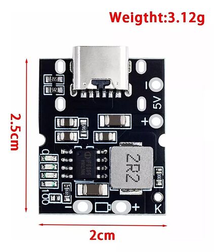
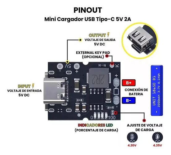
The web site gives all the necessary information in these jpg images (converted from the webp source)
this jpeg gives the board dimensions and component layout for the board. This one gives the connection diagram.
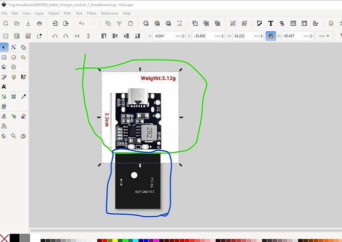
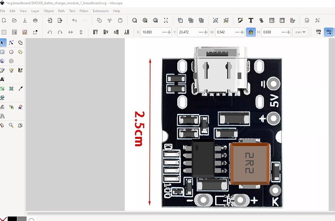
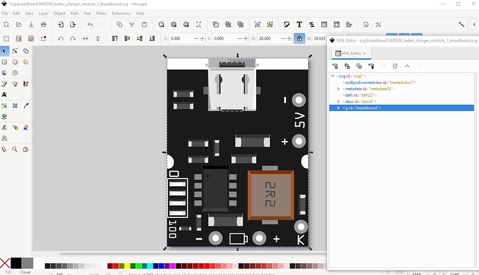
from them we create a breadboard image like this and then import the jpg in to Inkscape to create the breadboard svg. Here I set the board to 20x25mm then scaled the image down to match it.
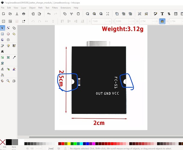
them change it to a path and add the two mounting cutouts.
then move the path to the back to leave the components in the jpg in the foreground and copy appropriate parts over them
like this
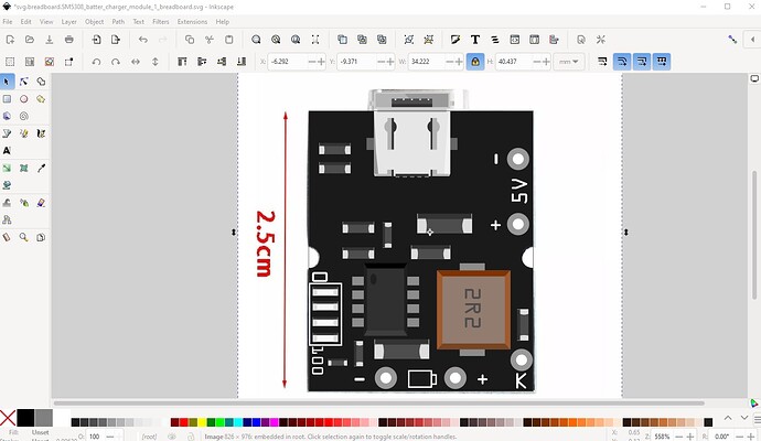
which forms a breadboard like this
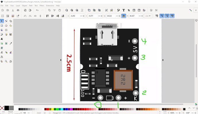
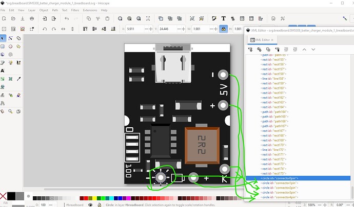
move the pads to the bottom and number them connector0pin through connector5pin
delete the jpg which leaves the breadboard svg
with the pins at the bottom of the svg like this
save that as the breadboard svg. Use Randy’s Inkscape extension to make schematic, then copy the breadboard svg to pcb svg and edit it to create the necessary pcb svg and we end up with this part which should do what you want.
SM5308_battery_charger_module.fzpz (12.2 KB)
Peter
thank you very much for your help
Thank you so much for putting the charger board together. But I have problems opening a fzp file in Fritzing. It only says that I can open fzb, fzbz or fzpz. I am new to this all so I’m sorry if it is an easy fix!
That is because you are trying to open the wrong file try SM5308_battery_charger_module.fzpz (which is the part unlike the .fzp file) further down the post.
Peter
