I probably have a few spare from my guitars, because they are dc jacks. Yeah there are only two cables in the pedals. There is a great example here explaining it https:// youtu.be/ebHL0H9_2DA
Hello, I have just received a drawing from someone on a forum showing me how the screens should be connected to the arduino. The part I don’t understand is how the dc’s connect to one another and then connect to the arduino.
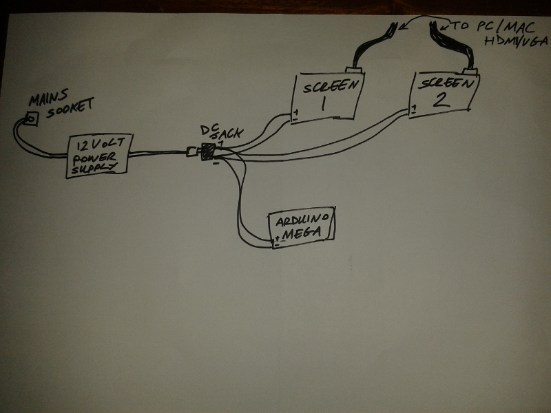
They appear to be implying that the screens want +12V to power them (I would have expected 5v, but if they are for a car then 12V does make sense) as long as you verify that is correct, because connecting 12 V to something that wants 5 is likely to blow it up), then you just connect the wires together such as 3 red wires to the positive 12V terminal and 3 black wires to the negative 12V terminal then one red/black pair provides power to each device. The one for the mega will actually need a 2.5mm coax power jack (as the wall warts have) on it I expect, the screens may have wires. As long as the 12V source can supply enough current connecting things in parallel to it is fine (but usually only for power, signal lines are not the same). The most useful part of this is the confirmation that the video signal is coming from an hdmi/vga connection from the Mac (not from the Arduino). The screens and the Arduino are being powered by the wall wart (12V power supply in the drawing) rather than the Arduino powering anything. If you disconnect the Arduino completely the screens and video (assuming the Mac is hooked up) will still work fine.
Peter
Something I don’t seem to understand is how exactly they go together. I understand what you’re saying. But do you strip the wires back of each to screen wire and join them together? But then even if you do that you don’t have anything to plug in. Someone said on the forum “A lot of those screens are designed for in car use so they run off 12 volts, so the easiest thing to do is get your screens and work out how much current they need and buy a suitable 12 volt power supply. You might be able to find an old laptop supply that will do the job or you can buy something like this https://www.rapidonline.com/powerpax-sw4380-desktop-power-supply-unit-60w-12v-dc-5a-c14-to-2-5mm-554671. Then you just need a suitable socket on the case to plug it in and run separate cables from the socket to the screens, the Arduino can also be powered by 12 volts via its DC jack so you can power that off the same supply removing the need for a separate 5 volt supply”
The starting point is the wall wart / Power supply. It supplies 12 V (if it is a wall wart probably to a 2.5mm barrel jack like this one:
(although you will probably need the UK version AC plug not US as this particular wall wart is). The barrel connector on the end plugs in to a socket such as this one:
http://www.bgmicro.com/PWR1168.aspx
and you can solder the power wires from the screens to the tabs of the socket. The arduino wants the same type of plug as the wall wart ends in so you would need to get a plug (of the correct size because there are a number of different sizes) that comes out to wires and solder them in parallel to the coax socket that connects to the wall wart. In the end all that’s happening is that three positive wires (2 from the screens and one from the arduino) are connecting to the positive end of the wall wart’s plug and the 3 grounds are connecting to the negative end of the wall wart, you are just using the socket to split the one connection from the wall wart in to three to go to the three devices in to whatever connector (bare wire, or a barrel connector in the case of the arduno) that they want.
Peter
Think I understand you, you strip the leads of the screen and solder them to the lugs then also solder the positive and negative of the arduino to it too. Tried to do a basic drawing on my phone not the best. I have just finished my circuit the same as the tutorial it works I think. Need to fully test it.
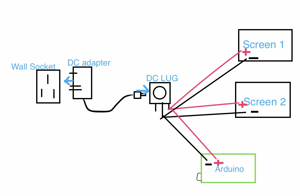
Yes this is mostly the correct idea. The connection to the arduino shouldn’t be wires (the raw input I don’t think comes out to the connectors) but rather a plug like that on the DC adapter that plugs in to the socket on the Arduino that would take the same plug as the DC adapter has. Connecting 12V to one of the 5V connections will blow up the Arduino. From the Amazon documentation on the screen I couldn’t figure out what its power connection is. They seemed to say it was an RCA jack, but that is a very odd (and I think dangerous) choice it mentioned a “power cable” but doesn’t have any details about it. That may come out to wires that could be soldered to the DC LUG in the drawing above. Good to hear the circuit is working, does that include the video connection to the Mac? The listed screen seemed to only have a VGA connector not hdmi and I’m not sure if the Mac supports VGA (it may well, I know little about Macs but something to check before buying a screen if you haven’t yet  ).
).
Peter
Glad I understand that, but now I don’t understand the arduino. I know they aren’t connected straight from the arduino but can’t I not just use jump wires from my positive and negatives. Like jump them from my breadboard? If you understand me. Mac supports HDMI but not VGA. Can buy an adapter for it to support VGA, I would like to use HDMI really, but then again. My mac only has one HDMI slot. Don’t know how I’m going to split the views of the program (plugin) to each screen. Yeah I got my circuit working this afternoon. Did the original tutorial one on breadboard. Only thing I didn’t add was the screen because I didn’t know how that connected but now I think I do just don’t know now with the arduino like you said earlier. I edited the original arduino program to what buttons I wanted to assign to each port and also added the led. So when the mode button is pressed it would light up and when pressed again it would turn off. Every button I pressed flashed on the arduino and also on my audio interface so I did send midi information. Which is a good sign. Just need to setup ableton and mobius to the correct settings before I fully test it. Then hopefully from there I can add more pedals/led’s and change what the led’s light up to etc
<img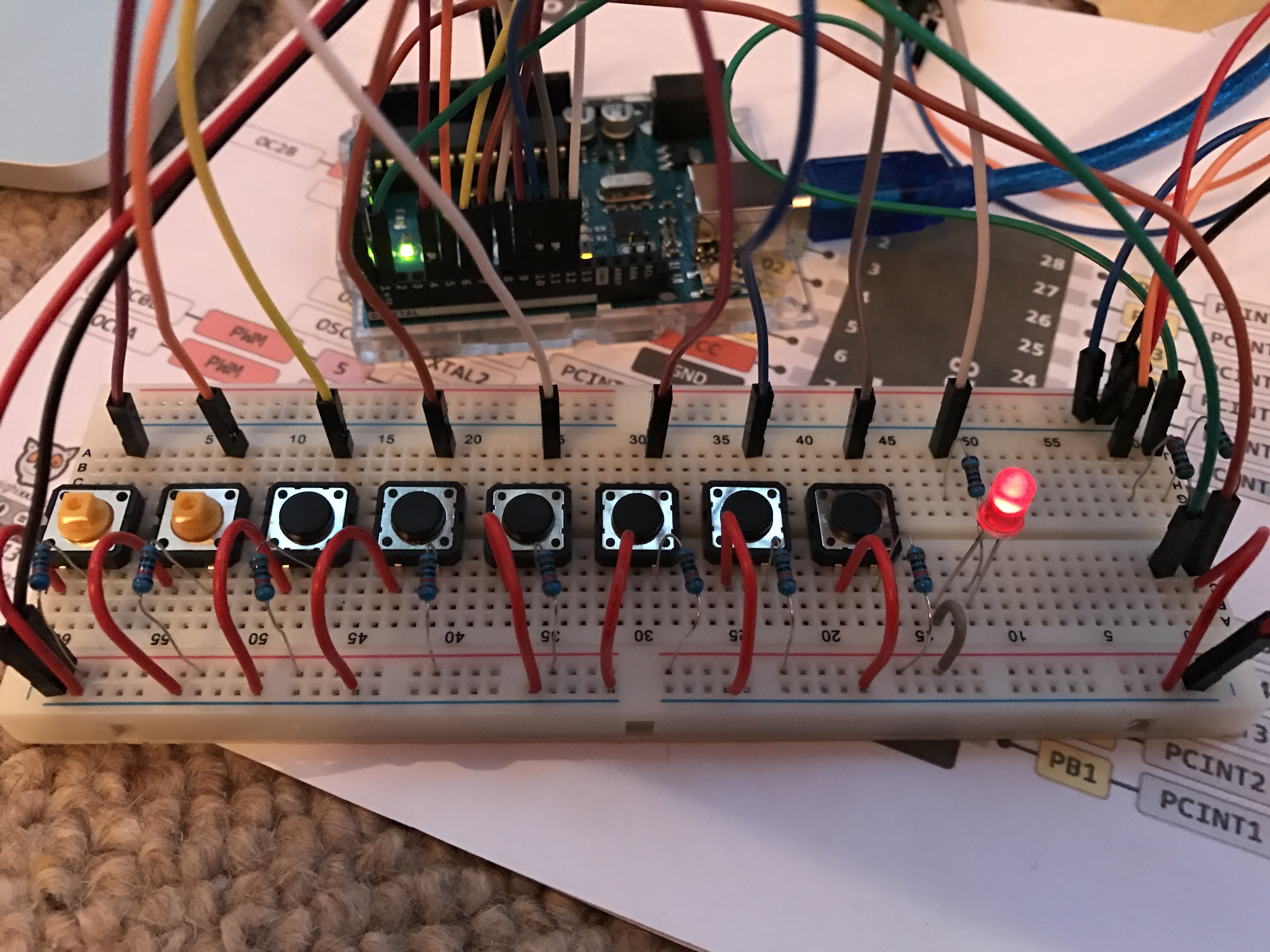
For the hdmi (remembering I know only a little about hdmi ) I think this is what you want (noting the warning about the two output devices needing to be the same which may affect you):
It would probably be best to ask the folks that have done this what they used to split the hdmi output. Some of the screens you showed earlier have hdmi input, one of those may be as cheap (and less hassle to set up) than an hdmi splitter in to a vga converter. As to the Arduino there are 2 on board regulators, one which takes the 9 to 12 v from the coax barrel connector on the board (which goes through a diode for polarity protection) and then does appear (but without the diode for protection) on the pins as Vin. You could hook your 12V supply to the Vin pin, but it would be safer to solder wires to a barrel jack (similar to the one from the DC supply that the 12V plug that powers the video) on to the plug where 12v comes out. Then that barrel jack plugs in to the jack on the Arduino where it is expecting to see 9 to 12V coming in which it polarity protects with the diode and feeds to the 5V regulator (which in turn feeds the 3.3V regulator) to provide the 5 and 3.3 V power supplies in the Arduino (using the jack also shuts off the 5V power from the USB cable if it happens to be plugged in as well which is a good thing too).
Peter
The guy who did the original tutorial used only one screen and he used a vga adapter to his mac for the screen. I understand what you are saying but I’m a bit lost as to how the positive and minus connects to the barrel dc jack lug from the arduino. I now understand how the two screens positive and minus connects to the lug. Because you strip them and solder them to the positive on the lug and then the negatives to the ground lugs. Think I’ll order some screen when I know what screens to get. Need to know which size yet
That will work fine, you don’t need the splitter or the second screen in that case and there aren’t any splitter issues. With the splitter both screens will display the same data (but the splitter then needs both screens to be identical) so I’m not sure I see a point to doing that. If the second screen is supposed to display something different then you would need to figure out the source of the different signal. As to the power jack you need something like this:
(just the first example I could easily find) the plug end goes to the Arduino and the wires end (which you need to make sure are the right polarity for it to work) go to the same place the screen wires go. The barrel plug/jack part of this article from Sparkfun may also help. I believe the Arduinos want positive on the pin (the center of the cable)
https://learn.sparkfun.com/tutorials/connector-basics/power-connectors
Peter
I need both screens to show different. But need to show the same program some how. I know how to get one view on the program but not sure how to get the other view. It could possibly be another program. So I connect that barrel male adapter into the arduino and solder the wires to the dc lug?
This is the part I don’t understand ![]() , if the screens need to show different things then I think you will need two hdmi outputs from the Mac a splitter won’t do the job (it will only copy the same data from one screen to a second screen which isn’t what you want). That is what you need to find out from the folks that have done this I expect, I probably can’t tell you.
, if the screens need to show different things then I think you will need two hdmi outputs from the Mac a splitter won’t do the job (it will only copy the same data from one screen to a second screen which isn’t what you want). That is what you need to find out from the folks that have done this I expect, I probably can’t tell you.
Yes that is correct. That gets the 12V (in a round about way) from the barrel plug on the adapter, through the socket (powering the 2 screens on the way by) and then back in to an identical plug to that of the adapter to plug in to the Arduino. If the screens didn’t need power you could just plug the plug from the adapter directly in to the Arduino which in the end is what is happening.
Peter
This is the thing, it hasn’t been done by others. Can only find ed Sheerans loop pedal with two screens in it. I’ll have to show you some images when I can get them for you. Only found that one tutorial that has a screen in it. But I want to build a replica of Ed Sheerans. I’ll get some more info to you later or tomorrow. Thank you starting to understand a lot more now with your explanations.
Images probably won’t help, as I don’t understand where the data is coming from, so seeing it there won’t help. You are going to need to find or figure out what generated the data and what it outputs it on. I think you may find that what ever machine ed Sheeran has uses two video boards each with an hdmi or vga output to one of the screens and probably two different programs each driving one of those video boards / screens. You will need to duplicate that on the Mac end of things and then the output to the screens on your pedal is just the two hdmi cables (possibly converted to vga if thats the screens you get). The hard part I expect is going to be finding out where the data comes from and getting it to the appropriate hardware on the Mac (and / or getting the appropriate hardware for the Mac if yours doesn’t already have two video cards). I’m unlikely to be useful there.
Peter
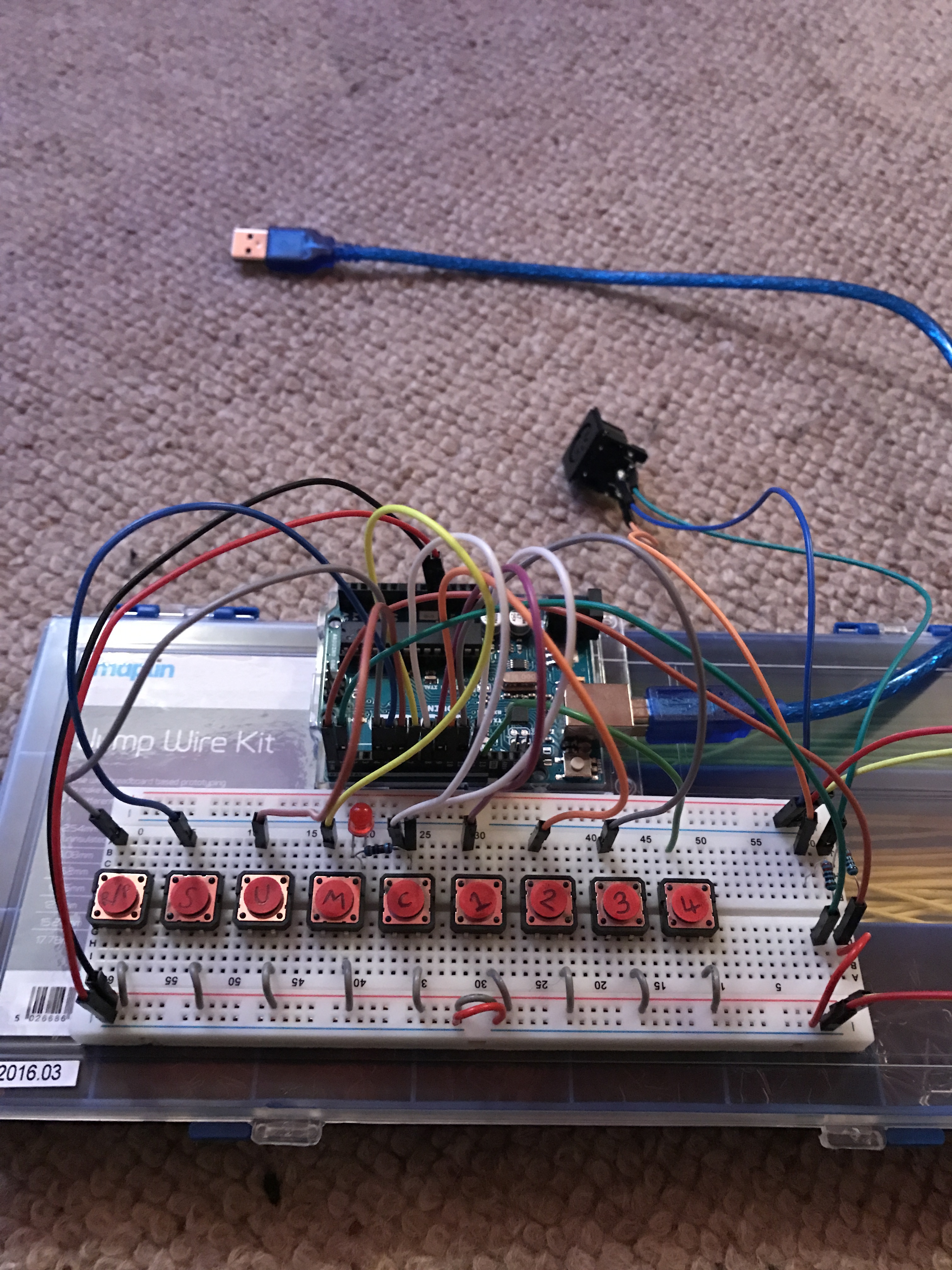
Hello been awhile since I have posted on here. I have been tinkering away. I have managed to build my pedal on breadboard haven’t added any screens. But it all works. How do I go about putting this onto perfboard now? People have been suggesting for me to using an arduino mega but I herd you can make them on perfboard
The perf board is potentially pretty simple, but lets look at build a cpu against buy a cpu first. While it is entirely possible to build a Uno (I don’t think you need a mega for this) on perf board (as the original person did) it doesn’t usually make sense. For around $2 US you can buy from ebay a complete Arduino nano. On a board the size of about a 24 pin dip you get what amounts to (and more importantly programs like) a uno. To do the same on perfboard you need a 328 CPU $4 in small quantities from digikey, around $10 with the Arduino boot loader loaded in to it. Then you need a 16 meg crystal, a couple of caps, a socket various pins and bits. I doubt you will get away with much less than $20 and now you have to build it (so add in what ever your time is worth). Once that is done then you have to arrange to program it which is non trivial too. That $2 nano (which have all those plus the programming) looks much more attractive to me. As to building on perf board, go back to your version that has the schematic with no breadboard connections. In breadboard view delete the breadboard and replace it with one of the perfboard options from the core parts bin and wire up your circuit on the perf board instead of on the breadboard. Then copy the diagram in to real life perf board and solder it all together. They also make perf board that has the same pattern as the breadboard and you can just move your circuit from the breadboard on to the same places on the perfboard and solder it down.
Peter
Okay I think I understand you, the reason why I’m asking about a mega is because I still want to add a few rgb LED’s the light up different colours and also I need to find a way to light up the logo and that is it. Still need to add the screens but that’s only the power. I’ve been trying to look up these perfboard methods but I don’t get how they work. I’ve still to put pedals to it but I’m not sure how they wire up. Think they have 3 cables. Or I could go down the option and use mono jacks for them but again I don’t know how they connect to the circuit either
The pedal that you referenced only has two wires coming out of it (its a mono jack thus two wires). I think the “polarity switch” they refer to changes the switch contacts from normally open to normally closed (as that is the only thing that will work with only 2 wires) thus one direction or the other of the “polarity” switch will be the same as your current switches. As to how perf board works if you get one that is the same as the breadboard, there are two strips of copper horizontal (the two power busses) then 5 hole strips vertical (the 5 vertical connections on the breadboard a space another 5 vertical connections then 2 more horizontal power strips. you solder the components to the perf board the same way they connect to the breadboard but instead of plugging them in to the breadboard you make the same connections by soldering them to the perf board. Technically you don’t really need perf board. You can wire one end of the pedal to ground (all of them together just like the power connection) and the other end of the pedal to the port connection on the uno just as your switches are now and that should work. I expect a nano will have sufficient connections to drive the leds you want, but you would be best to test that on your current setup before commiting one way or the other. You may have to do some port expansion to get enough ports, but I expect you won’t need the larger memory that is the main advantage of a mega (but I also may be wrong here ). I’d try it first on the uno before committing to a mega.
Peter
Okay so I think I’m going to go down the jack socket route. I need 10 pedals which will cost me £130 and I don’t want to go stripping the plug of to void warranty. So I was thinking of getting these 6.5mm female mono sockets.
http://s.aliexpress.com/ia63uYFJ Will these work? I don’t know how to connect them to my current circuit. Seen a few diagrams as to what each leg connectivity is. And I’m going to get these pedals here. Sticking to Roland boss pedals which are one of the biggest makes of pedals. https://www.roland.com/uk/products/dp-2/. You are correct the pedals do have two wires. I think you can find the polarity of them online