How does connector0terminal work in a generic IC in SCH view
I can see how a pin works in a big part like an UNO, ie, connector0pin is a sliver line, and connector0terminal is a small tip rect that auto assigns so that all wires connect to the tip, but the generic IC seems different.
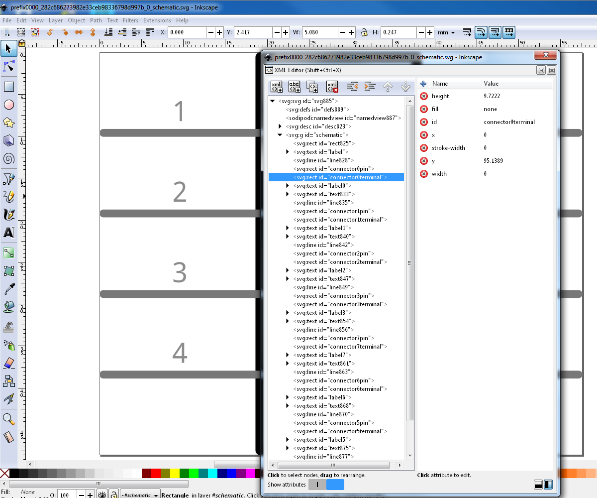
It has a sliver line, and invisible none stroke none fill connector0pin on that line. But it also has a totally invisible connector0terminal somewhere - I can’t make it appear -.
I think this is the code. <rect width="0" y="95.1389" stroke-width="0" x="0" id="connector0terminal" fill="none" height="9.7222" />
Usually when you select an object in INK XML Edit with no fill and stroke you see a dotted outline and large arrows to show you where it is in the dwg. But when it has no fill and stroke, plus no stroke-width and width, it doesn’t show anything, not even the select arrows. It doesn’t explain why INK’s arrow button’s toolbar dimension sizes and position boxes don’t work, and that only changing the object’s stuff in XML Edit makes it do something.
Now the problem is, how does it assign to the end of the pin when in FZ Part Edit it shows the assign cross-hair in the middle.
Inkscape does not handle elements with zero width or height (cannot select according to FritzingCheckPart, your symptons says will not display graphically view even when selected by xml), but that works fine in a Fritzing Part. Parts editor might have issues creating the part. I don’t use that. I also don’t use zero sized elements.
That svg terminal element has a height of 9.7222. The cross hair will be in the middle of that, at whatever the distance that means for the image file. I use a square rect element for connector terminals, with small dimensions. The cross hair, and actual connector endpoint, will be the middle of whatever element is used.
That’s what I would expect, it’s just that it’s not what FZ makes when it makes a generic IC. I’m not actually creating the IC in FZ Parts Editor, I’m just pulling the std IC into BB view, Edit, and selecting “show in folder”, and opening it in INK.
Whatever size and position it says in INK XML Edit, isn’t what is shows in the arrow-select size and position toolbar. If you try to change size and position in the toolbar nothing happens, but if you change size and position in XML it actually does stuff.
Another weird thing. if I draw a part and just leave the pins paths, then assign the pins in FZ Edit, it renames the pin connector0pin and puts a small connector0terminal on the tip.
I was thinking the connector0pin is for the colour and the connector0terminal is for the connect, but even though the UNO has the same connector0pin/terminal, if you look at the pin indicator colours the UNO doesn’t have the unconnected red status colour.
This is the problem. Inkscape won’t display or select (so you also can’t move this by dragging) a 0 length or width element. Check part will change this from 0 to 10 (so a 10 thou rectangle if the scale is correct) but anything other than 0 will do. I eventually aim to correct that in the parts factory code but haven’t gotten there yet. You can select the element and move it via the tool bar though (just not graphically.)
Maybe because I’m using INK 1.1, but the toolbar is totally dead if you type anything into it. Only after I edit the 0 width in the XML Edit does the toolbar start to work.
Does anyone know how they are suppressing the pin indicator colours on the UNO - and most other the big parts -, in FZ. I copy their connector0pin for the pin path, and connector0terminal on the small rect on the tip, but I still get the red pin.
I put the UNO SCH svg into a generic IC, and the pins do the normal red thing.
I put my svg - it red pins in a generic IC -, into the UNO part, and no red.
Yeah it must be the fzp.
I don’t know what I’m looking at in the code, and I’m not going to try and teach beginners how to hack the code - we can’t get them to make parts, yet alone doing that, lol -. So I’m just going to tell them to use an UNO part or similar if they want that style of indicator pin.
EDIT - is there a quick way to edit all those females to male so I can test it.
The fzp file is also xml, which is just text. Any text editor (like notepad on WIndows) with global search and replace should be able to do it. Simply replacing ‘female’ with ‘male’ might do it, but could change unintended text (in the description or tags for example). As long as the editor can use quotes in the find and replace, changing ‘type=“female”’ to ‘type=“male”’ should both work and be safe. The outer single quotes in that are my markers, to show where the strings to work with start and end. Depending on the editor, they (or a variation) may or may not be needed.
I did it manually in Wordpad, but now it won’t let me Send to/Compressed (zipped) Folder, ie, I can’t zip it. Oh well.
EDIT - I also found a bug in FZ 0.8.3. If you bring in a 100 pins svg, with the pins already assigned in INK, to an 8 pin generic IC, and change connector # in FZ Edit to 100. FZ looses 1 pin. In BBview INK svg I had to skip pin 50 and go from pin 49 straight to pin51. Then when I brought in the 100pin SCH svg, it lost pin8. I set an IC to 100pins and Edit that, and it doesn’t skip pins. Oh well, we learn something new again. DIP - 8 pins to 100pins.fzpz (9.6 KB)
Wordpad is not a good choice for editing plain text (including xml) files. You need to be very careful to save as plain text, otherwise it will try to add document formatting that will break the xml.
Doing the zip is separate, and a function of the tools being used. Any file (maybe not VERY large files) can be zipped, including other zip files. The way to get there, and potential limits on what is possible, is dependent on the programs used.
Any particular reason you are using version 0.8.3? or was that a typo?
I don’t think you can suppress it entirely, but if you reduce the length of the line (or path) that makes up connectorxpin you can reduce the size of it. If you change the connectorxterminal to connectorxpin and remove the terminalId definition in the fzp file the red/green parts will be only the size of the terminal definition (which needs to be square to get the wire to connect correctly.)
I’m not good at XML and it’s the closest. I don’t do any formatting change in WP.
I swear I used to zip them that way in 2015 - that was the only way I knew to make parts back then.
I don’t actually use FZ anymore - I barely do any electronics these days - so it’s not worth upgrading. I’ve also spent maybe 1000 hrs helping here, so I’ve probably paid enough.
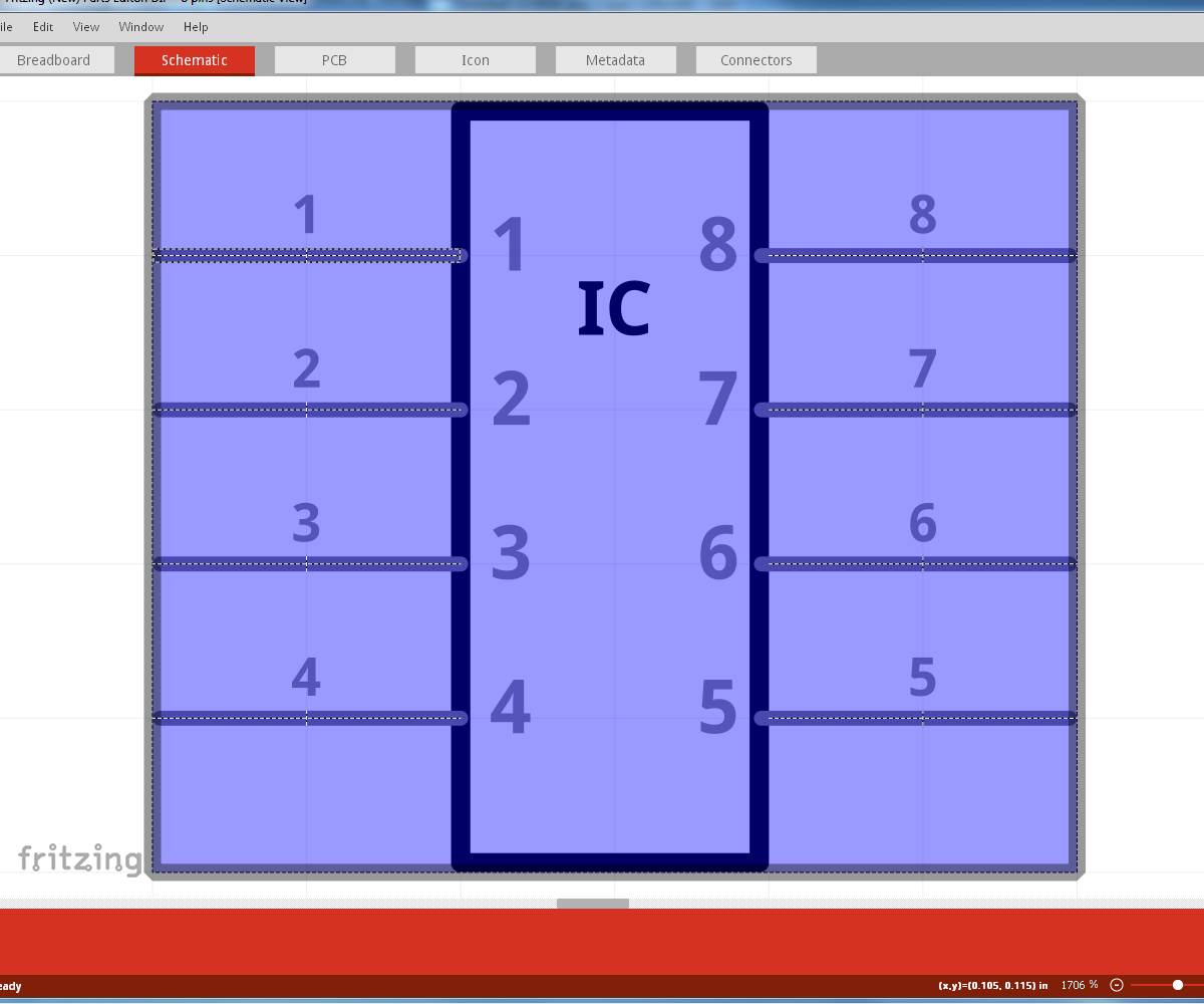
Actually, in SCH of the UNO, or any Arduino, the pins have no colour in the non-connect state - pic above -. And it’s only after you connect stuff does any colour show. Generally in SCH tip allocation is not common, it’s either full pin colour or no colour, ie, like in shields. I’m actually doing a vid showing the 3 types of pin allocation.
I can’t really show XML coding to beginners, because it’s hard enough to get them to realise things like a svg is not the same as a raster. I had to make a vid on how to search for a part, that’s how bad it is.
I’m actually a bit sick of people always asking for parts and not even attempting to make them. Like what’s going to happen when you 2 experts are gone - I’m going after these last 2 tut vids -.
If you ask me FZ has a lot of problems. It looks simple to use, but part making is horrendous if you don’t have experience. It either needs a full and simple set of instructions, or a simplified internal svg editor, because multi step to make parts with no instructions is driving people away. That’s why my new vids are the most simplified method as possible, because you are dealing with totally blank people.
EDIT - I worked out how to stop the IC label offset in 0.8.3. Make the IC vertical in SCH before making it 100pins. It seems it’s only horizontal ICs that can glitch.