I got some non polarized parts (resistor, relay, condenser, …). When I layout parts on the pcb, I first try to have the minimum of crossing “dash” lines (to ease the routing).
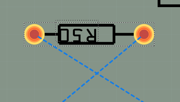
For simple parts (symmetric like resistor) I can simply rotate 180.
From this
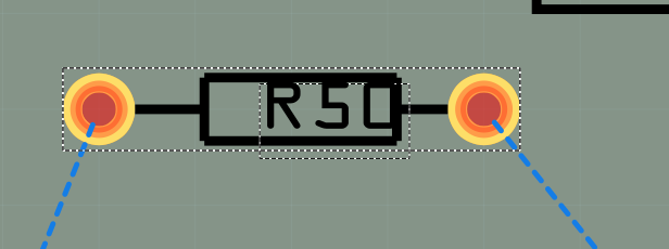
To that
But for the more complex parts, like Relay, this often implies to swap part connections on the schematic, and swap again and again… until I find the design.
Are there any options in the part design (or maybe in sketch also) to describe connectors as “alternative”. Then Fritzing can choose the closest one to draw the dash lines ? This makes me think a little bit about buses, where Fritzing choose the closest pin of a bus to draw these line.
I also have the case with the controller (arduino), where two I/O pins can easily be swapped. No matter if D4/D5 are swapped, as it just requires to adjust the C++ code.
It is not clear to me what you are referring to here. Can you provide a sketch or an image (preferably the sketch) which illustrates the problem you are trying to solve?
No, connectors are must be unique in a part and have no option to be alternative.
The rats nest lines are drawn to the closest connection to the same net now.
But you can not swap D4/D5 on the physical board as they are in fixed positions and Fritzing is dealing with the physical board.
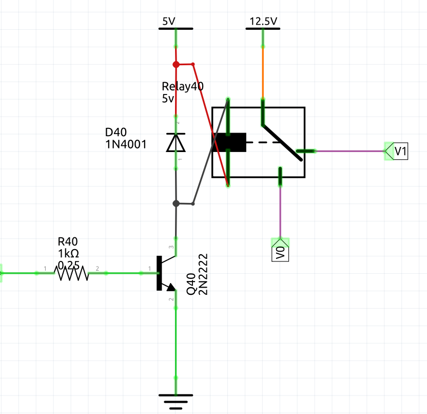
Q40 connector2 connected to Relay connector0
Relay connector1 connected to VCC
Regardless of the diode, I don’t really mind which connector of the relay goes to vcc. What a care a lot about is if I connect Vcc to connector0 then connector1 need to be connected to the transistor. So when connecting Vcc to the relay connector 0, I expect to see a rat nest lines from relay connector1 to transistor connector2.
As you can see in this picture, during the routing, I decided to swap the relay’s connectors to ease this routing, but now my schematic view is “messed-up” (lines are crossing) and it’s useless…
Assuming the relay pins were swapped to make pcb routing easier, the only solution I see would be to have a different relay part that inverted the coil connections in schematic. There doesn’t seem to be any rotation or flip that will correct this. It is basically a limitation of how Fritzing works. After doing the switch in pcb you would need to do a delete minus of the relay then add the alternate part and reconnect the wires (which would now be in the correct direction in schematic.) The down side is you have multiple versions of the relay part.
Pins in PCB have to be the correct position for PCB. Schematic parts (or sub parts for things like relays) can be rotated or flipped for convenience. There is no way for the current version or Fritzing and parts to do that automatically, because Fritzing has now way of knowing when it is safe to do so. There is nothing in the part standard part definitions that show that there is an electronic part between 2 pins, and that polarity does not matter. SPICE information can be added, which might include that information, but attempting to reliably make use of it to automatically reverse which pins to swap to reduce the length of ratsnest lines would need a lot of new code. In general, people can see the graphical image, and realize the rotating 180° is electrically equivalent to swapping the pins. The code does not see (process) the graphics at all. It works only from the defined connectors. SPICE has additional information to work with.
Since hovering over a connector displays information about the pin, swapping the ratsnest wires would be wrong anyway. It would be very confusing, even if electrically correct to display a different pin number for the end of a resistor that is connected to the capacitor in breadboard and in schematic view. It would have to be a rotate, or the connector information would need swapping. That still leaves out issues with parts that have labels as part of the graphics. A swap would break the intended association between the graphical labelling and the connector.