I took the gorn’s out… they are not needed, FZ generates them and when I use files that FZ generate in CorelDraw, the gorn is labeled as svg tags of some kind and cannot be extracted from the element. The only way I can delete them is in a svg editor. Most of the time I just leave them in as they don’t normally cause a problem.
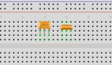
Attached is the part file for a 3-pin Bussed, I have been screwing around with it for hours trying to figure out how the get the “spice” to work for the resistance and tolerance. It keep jumping back to the single resistor. This works under the family “resistor” along with the other resistors. You probably understand this better than I do. If we can’t tap into the spice for the single resistor, then may need to use a new family name like “resistor-array” for both the Bussed and Isolated and write a new spice. Supposedly you can create your own spice, I just don’t know how.
You can load this file into FZ and see what I mean. Get this down to a science then we can work on the smd packages.
Ah. Got it. Sorry, I didn’t know what to do with it. I’ll remove it from my script.
I’ll complete the script for generating the other views out of what you just sent me during the week and then complete it to make one neat package.
Regarding SPICE: I honestly have no idea. I never used it really (maybe two times during study but that was it). I’ll first have to make myself more familiar with it. Is this a requirement or just an added bonus?
Here are the 2 resistor files, Icon is just a duplicate of breadboard. I included both bussed and isolated schematics. I also cleaned up all of the gorn tags.
schematic should be in the schematic layer… although it works without it…
breadboard should be in the breadboard layer.
pcb needs to have the silkscreen layer and the pins embedded in the copper1/copper0 layer.
Awhile back I bought an RPi just so I could play around with Python… I loaded Python on my PC but I never got a display and usb keyboard for the Pi. That PC died and I never installed Python on this one yet. Sometimes my poor-ole-brain just does not want to absorb all of this stuff…
Assuming you are running windows, cygwin is a good way to get Python or perl. You get a (mostly) Linux environment integrated with Windows www.cygwin.org. I run it on all my windows machines.
Well, did you get it all figured out? I create parts similar to the core parts; make all the view files and the .fzp then zip them all up into the .fzpz and skip the parts editor all together. I guess you figured that out by now.
Have any luck with the spice thing and getting the resistance and tolerance to work?
I had Python on here all the time… don’t know when I loaded on here. I loaded PiCharm Edu on here too as a coding refresher course… Maybe I will get back into it a little bit… Always wanted to learn Python…
Sorry for my late response. Shedules are getting a bit tight here. After the weekend my day should be much more free. I’ll keep you posted.
Getting the svgs to work is really no problem at all – just a bit of work. Making the actual package will take a bit more practice to port over to python. I’ll wrap my head around that after creating all the images.
Regarding Spice: I’ll really have to do some research here. I do not have any knowledge at all about that – although the corresponding course was only two years ago.
Are you guys trying to make an internal part that uses a 1 section svg that is stacked when you select the pin count, like a header, but with 3 parts, or is this some external script to make the svg.
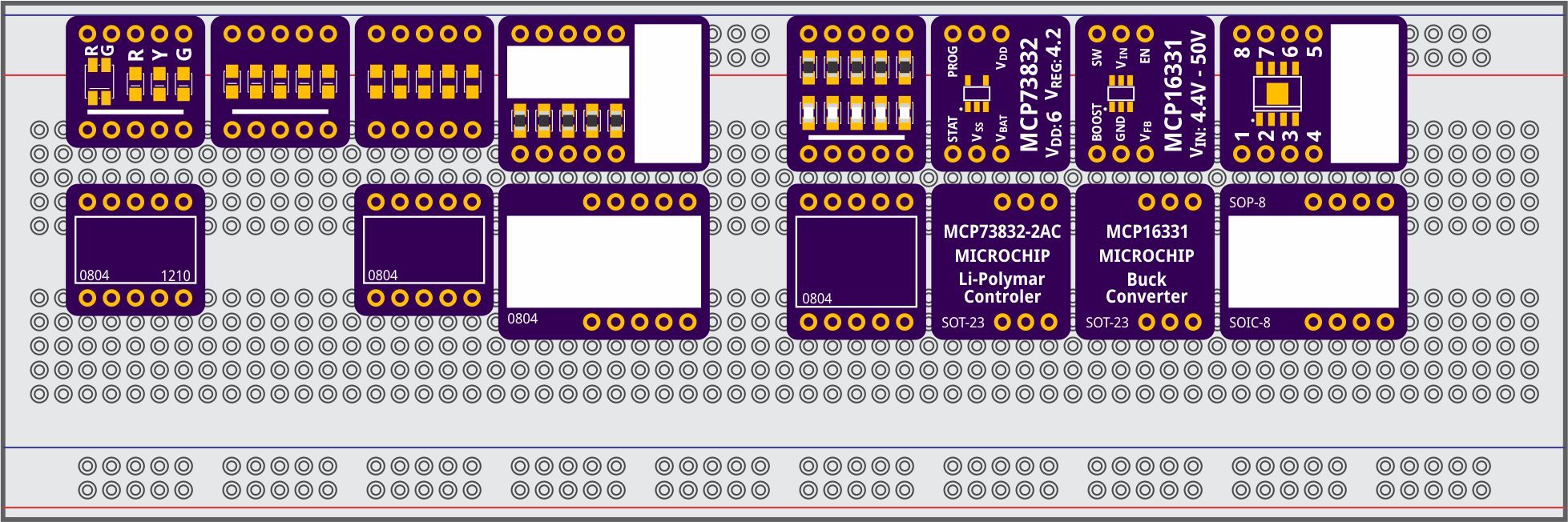
after a bit of silence I’m back with all required SVGs. PCB, Breadboard, Schematics and Icon are generated. Do you spot any errors? If not, I’ll proceed in trying to package everything up. Is there anything new on SPICE that I could include in those files?
I’ll be back with more if everything goes well. Else I’ll be back with questions.
He didn’t draw the PCBs… FZ did… I modified it and Heinzelchen wrote the Python script that generated multiple pin holes. I used a 3-pin generic connector from the FZ core library and altered it to be used in the Python script. When I work on drawings that have a white lines, I always set a dark background so I can see them… Tricks of the trade.
@Heinzelchen , we did figure out the SPICE thing, Now I am working on the best way to organize the Resistor Family with all the different resistor configurations so the Resistor Family doesn’t look like the Connector Family… a cluttered mess impossible to navigate… I will send you a template when I get it together…
Yeah I know it’s one of the old parts make with that old drawing software with the dark background, but now that FZ recommends Ink it causes problems for beginners, because they don’t know it’s there. I remember the first part I modified because when I opened the PCB svg, it was just 4 gold contacts in much bigger a rectangular box. It took quite some time to figure out there were outlines of the part in there. I always convert it to black when I find it, just like FZ recommends in part creation, and in Ink you just select silkscreen group in XML Editor, hold shift, and click on the black colour box on the bottom colour bar on the left, and everything in there gets a black silkscreen.
Rookie is exactly right. I can build you a 3000 ton bridge and fix a Nitro Top Fuel head with a hole in the side the size of a golf-ball, but 1 year ago I didn’t even know what a svg was. It took 3 months to make a FZ part from scratch because there was no help or info back then, so I had to learn Fritzing, Inkscape, XML, Electronics, KiCad, Eagle, from scratch and with no experience, to be able to reverse engineer a FZ part to actually make it. I kept asking for help on the forum, but there was no response, so I keep hacking until I made a part. Back then they closed the part side down - they make their lively hood from part creation so I don’t think they were keen on helping part creation - , but after I posted my working part and started telling people how to do it it took off. After that the FZ guys got more serious about parts and made the part submit and started helping somewhat.
I remember seeing that empty svg and with nothing to click on, because you couldn’t see anything, and was wondering how it was added, because it was in FZ. Was it another svg, was it internal to FZ, when you don’t know anything you don’t know what to ask. It was a couple of days of getting nowhere that I found in a searching that old parts had a white silkscreen.
Unless you’ve been a rookie you can never understand what it’s like, so I always correct stuff for people that are starting from nowhere, just incase.
I also wondered about the silkscreen actually. After looking in the code it became clear to me, so only working with code and not visually pays of in a way.
It’s no problem for me to change the color to black, if this is the default for the future. Just let me know.
I just never paid any attention to it and usually left them what ever color they were. They are always black on the view regardless what color you draw them. Although, sometimes I draw them white as they give me an actual representation of what it looks like when printed…


 Too many irons in the fire…