Parts Properties not working on Mac

I’m using Version 0.9.6 on macOS Big Sur 11.2.3.

Several parts do not recognize changes to the Properties. For example, if I select a basic resistor and change pin spacing from 400mil to 100mil (stand-up right), nothing happens.

Same with Generic female header. Although it does update if I change from female to male, I cannot change it from single row to double.

Am I doing something wrong or is this a bug?

While I am on Windows rather than a Mac, here is one (common) possibility: are you trying to change the properties while still in the parts bin?

Here I have selected the resistor in the core parts bin and I can not change its properties in Inspector. To be able to change the properties I need to drag the part in to the sketch

Here the resistor is dragged in the the sketch and when selected in the sketch I can change its properties (resistance value, power and part number.) which I couldn’t when it was in the parts bin.

Here I changed all three fields. If that isn’t the problem, then it may be a bug and we would need someone on a Mac, but this is the most common reason for not being able to change attributes.

Peter

Hi Peter,

No. I have dragged the part to the breadboard before changing properties. Keep in mind, I can change some of the properties but not all. I can do a video if that would help.

Thanks for your help!
Tim

Do you have an example part that doesn’t work? I can try it on Windows for you. It is possible that the part itself is broken (there are some even in core parts that we haven’t gotten to fixing yet!)

Peter

Yes, Try changing a basic resistor from 400mil to 100mil (stand-up right). Another one is the Generic Female Header. Try changing it to double row.

Also cannot change the Generic shrouded header from double row to single. Only this one is a little different. The select refuses to change where as the Generic female header the select does change but the part ignores it.

I believe that setting the resistor pin spacing only changes the pcb view footprint. Schematic and breadboard are not affected. The resistor has bendable leads, so it can be connected however you want on breadboard view. Though it might not be pretty.

The resistor not being able to stand up makes it hard to fit in the tight space I have. My situation is I’m using a perf board to lay everything out then will solder it up straight from the breadboard layout since the perf board does not translate to the PCB layout. If everything works as planned I’ll try doing a PCB layout and get one made. I’m a noob at this but having fun! :grin:

Yes, it doesn’t change in breadboard (and probably should), however it does change in pcb where it is important. I expect that who ever did it didn’t think breadboard was important.
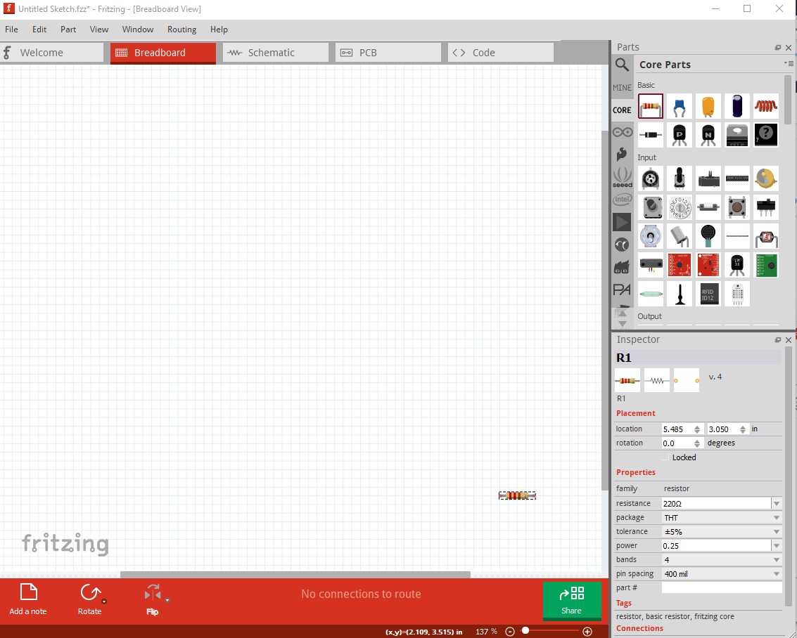
change to upright

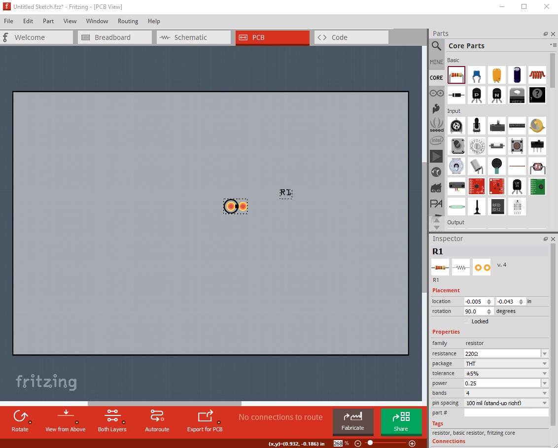
pcb changes correctly but breadboard does not

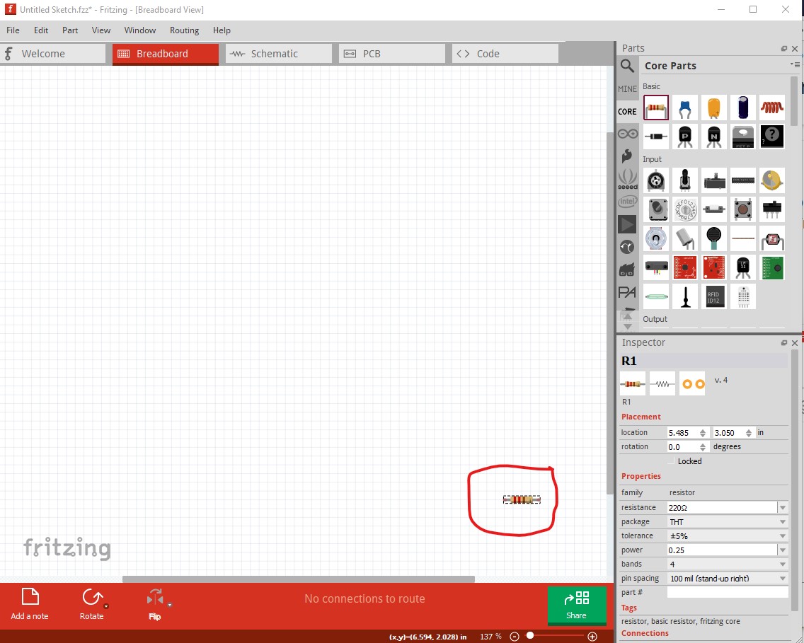
There is a custom part here:

and I later made a modification of this part that has the color bands included (although I don’t have the reference handy, it is posted in the forums somewhere :slight_smile: )

The dual row connectors are a similar issue. It was thought that dual row connectors should manifest as single row in breadboard and there are bugs in the code that make that work poorly (I asked one of the developers about this 4 or 5 years ago when there were still some developers around) That is on my list of things that we should fix but hasn’t been done yet. The code generates the generic headers on the fly, and the code is very complex. Again, pcb view works correctly just not breadboard.

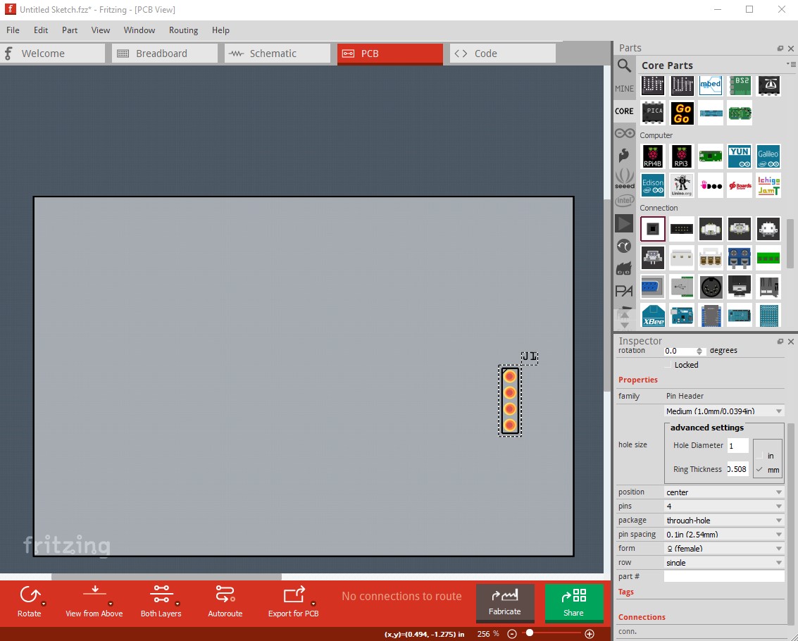
change to double row and pcb changes correctly

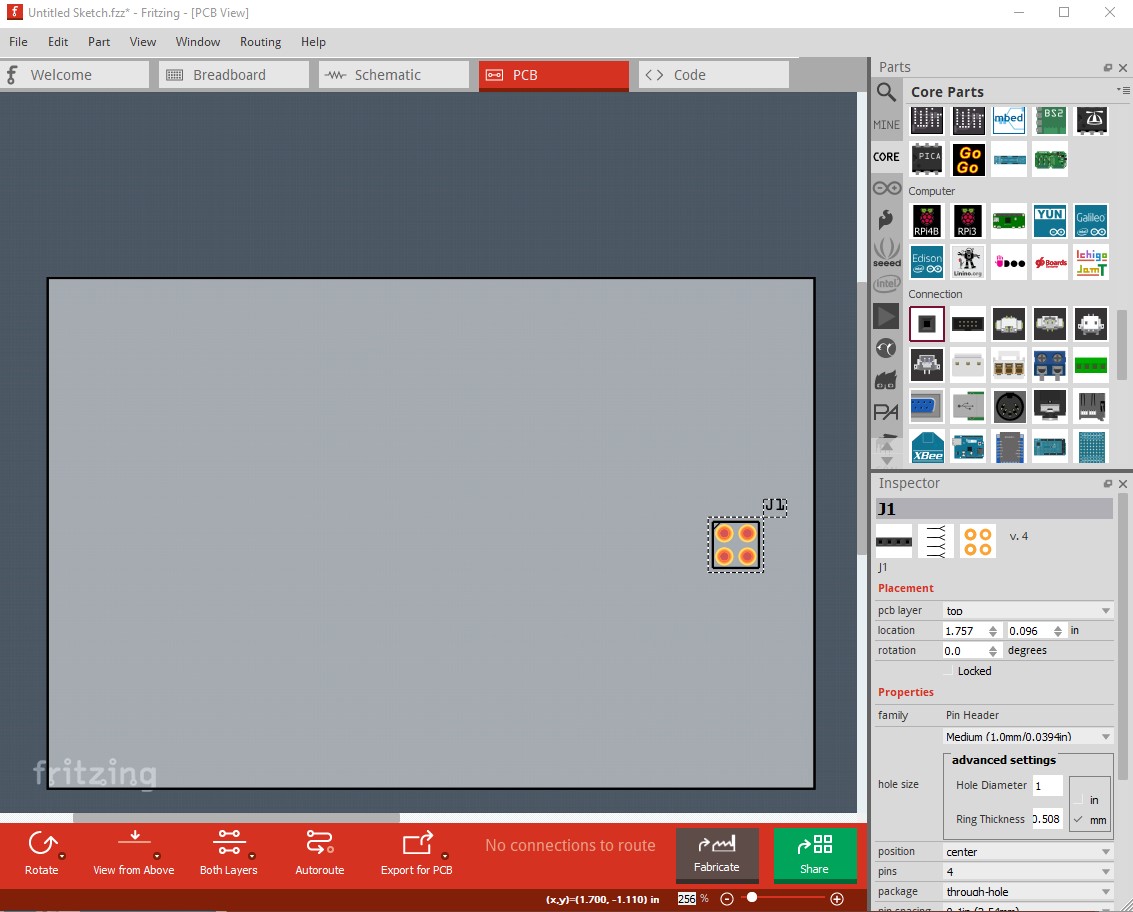
but breadboard remains single row (as noted by design although I think that should change.)

Peter

1 Like