Part Request | Avent Azure Sphere

Hi there,
there are a number of people that would need the fritzing file of the Avnet Azure Sphere development board. I have not found them anywhere and cannot make them myself. I was wondering if anyone would be able to help me.

The link to the board on Farnell is below. Thanks in advance.

Andrei Florian.

In order to make a part we would need a document, hopefully a mechanical drawing, that specifies the size of the board and the position and names for the connectors . A look at the supplied link indicates a number of different development kits but no suitable documentation providing pin outs and position of connectors. If you can come up with such a document I’ll have a look at making a part.

Peter

hi,
thanks for the reply, this link has a lot of documentation on the part.

Andrei.

That should be enough to make a part. I assume we will also need a part for the module it uses, as after prototyping on the dev board you will presumably want to make boards using the module. I’ll work on creating a part.

Peter

thanks a lot, that would be perfect

I hadn’t forgotten this, it just took some time as it had to be made from scratch. Luckily their documentation is good, so that was easier than it might have been. In any case here is the development board part and its test sketch. It has no pcb layer (although the headers in the test sketch show up in pcb), as it isn’t practical to put a pcb on top of this and that saved a bunch of work.

Part:

azure-sphere.fzpz (32.1 KB)

Test sketch to make sure it works.

test-Sketch.fzz (18.0 KB)

and for the rest of you a png of bb from the test sketch

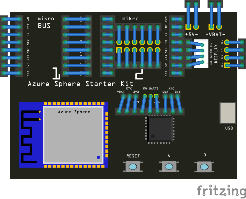
All the common pins have been bused, so if you click on a pin, all the other pins that share that pin should light up yellow. The description fields (if you hover over a pin in any view) indicate all the possible functions for that pin. If you or @KjellM have contacts at Avnet, they might be interested in pointing out a Fritzing part is available in their docs (and if they like Fritzing may be willing to provide support as well :slight_smile: ) because it would make documenting projects using their dev boards easier. At them moment I’m going to ignore the actual MT3620 part as it appears to be about 128 pins or so (and thus a lot of work) until someone actually asks for it. Hope this helps.

Peter

1 Like

Thank you so much,
It looks nice, the important thing is that we can use the MikroE and OLED pins.
Andrei.

Since you can in real life it seemed best if you could in Fritzing too :slight_smile: . If you find other pads that should be in but aren’t post and I’ll add them. There are some odd pads around the board that don’t seem to be documented.

Peter

DXF and STEP documents for this Starter Kit are posted under the “Technical Documents” menu tab at [http://avnet.me/mt3620-kit]

Yes I saw that, they also have a schematic somewhere. I’m not sure I have anything that will read dxf files though. At the moment the lazy bet is to have someone that has one tell me if anything is missing :slight_smile:

Peter

Don’t know how useful these files are but, not clear on what’s wanted (and currently I haven’t much free time ).

Opened the DXF and STEP files and exported as .PNG.

The DXF from the ref site should open in Inkscape.

Three files ( .PNG) below are:
3Dview of the STEP model
Top View of the STEP model
Top View of the DXF

Indeed, Inkscape will open DXF (though, I don’t remember if I installed a plug-in a few years ago. Probably not so, give it a try…) Below is screenshot of Import into Inkscape. I did not bother to change line color…

Thanks, I hadn’t thought of Inkscape. It loads but isn’t correct. The pads are in the wrong place mine is identical to yours above) . The copper layers haven’t been rotated somehow. The wireless module and the connectors at the top should both be rotated 90 degrees. Perhaps I’ll poke at the import routine and see if there is something I can do because that would be useful if it worked correctly. I see Infiniview will also open it (but needs a plug in I don’ t currently have). FreeCad opens it correctly but won’t export it as an svg. Sigh! So many incompatible tools :slight_smile:

Edit: the importer says it has limited support for blocks and that I should use “explode block” first (which would require something that understood blocks of course), so I wonder if that is the issue. Don’t seem to be any obvious controls in the importer.

Peter

… couple of things…

You can Import the .STEP into FreeCad and create an .STL
(requires knowledge of how to do it…). Resulting .STL shown below.

Then, open .STL in a program that Heals .stl (such as NetFab).

Then, export the Healed file as .STL or .OBJ

Then, (from reading Posts, Inkscape has an extension to load .OBJ but, not my older Mac version (“Share”, referring to below link is not available to me).
Here’s a link http://goinkscape.com/how-to-import-3d-models-into-inkscape/ , see Step#3

There must be other apps to open STL/OBJ/etc that can make a 2D drawing from it.

Lastly, in FreeCad you can import the DXF, clean it up (delete the stuff not needed) and if it’s clean enough, you can export .SVG from the Draft workbench. (NOTE: Though FreeCad has plugin’s that work in some common workbenches, while having common aspects, they are not reliable across all workbenches!!!)

Below show DXF loaded into FreeCad and some elements selected as if desired to delete them…

That last one is more like it should be. I’ll have a poke at this and see if I can create a tool chain to do this as it would be useful to be able to get pcb layouts from as many sources as possible.

Peter