Improved Micro:bit part

Yah, I don’t know of a way to delete it in Ink although there should be one, so I use a text editor too.

Ink has deleted the required duplicate pin labels (connector0pin needs to be both in the copper0 and copper1 groups and Ink won’t do that, it renames one on load.) It is an ugly way to go, but the only way I know to get top and bottom copper in a part.

Peter

You could try “save as” and specify “optimized svg” in Inkscape. I have not seen this particular case, but have found that path cleans up a lot of junk problems in Inkscape files. Just watch the options you pick in the configuration requestor. The choices are remembered between sessions, so you only need to get them right “once”, then just click OK after that.

I’ve used INK for years, but I’m still not good at it :slightly_smiling_face:, ie, it’s such a big program.

Someone better than me will have to fix this, because it need lots of changes in each view. I don’t even know how they assigned the pins in FZ BB view when the polygons are on a layer above the connector pin/terminal, ie, I would have to swap the layer heights for 100s of objects, and that’s not to mention the other views.

That will be great - thanks!

The bottom 3 rows are connected as shown in my photo; they are just for the user to add components as required.

Thanks for the help!

One problem with this is that it optimizes the copper layers and thus removes the stroke-widths from the pads (unless that can be disabled?) which breaks Fritzing unless you use FritzingCheckPart as the gerber code doesn’t inherit the stroke-width (check part does the inheritance so stroke-width is in the copper groups.)

Peter

Ah! I’ll correct this to reflect that. This one doesn’t have that, but does have the top two connected together and grouped and pcb removed as not useful, and the pin labels on both the top and bottom row in breadboard. Indeed wires are always on top so will cover the labels if the wire goes over the label. If you route all the wires down the top labels should still be visible.

edit: Yet another update to add the prototyping connectors as pins in Fritzing. They don’t appear in schematic, just breadboard and are bussed to match the pcb above:

Microbit-breakout2-complete.fzpz (26.8 KB)

If that is about using save as optimized svg, there are several check boxes to control the optimization. Unchecking the “create groups for similar attributes” might help for that. The big one that helps (for me) is making sure that “collapse groups” is checked. That and remove meta data gets rid of a LOT of the junk not needed for fritzing.

I should have another look at this, as I haven’t done so i a few years and things may have changed (as has my understanding of what some of the options do :slight_smile: ) I remember there was a catch22 that came up, if we enabled something something else broke but I don’t remember the exact details.

Peter

So we may need to document some of those, to say which scenarios it will, won’t, might not work. I can say that for the simpler case I have been working with, it has worked well, even with “create groups for similar attributes” checked.

From many other contexts, I like to move the common pieces to a wrapper of some sort, so that it only gets defined once. When that works. As you may have seen, I found a case with hybrid connectors where moving the attributes did not work.

Thank you!

I now have a few new (beginner?) problems, perhaps you can help?
First, when I tried to import the new file it complained that I already had a part with the same name. I couldn’t find a way to delete the old part.

Next, my parts panel disappeared and I can’t find a way to get it back! I have View set to show the parts.

I will try to reinstall Fritzing next!
Rob

OK I solved the missing parts panel (from Window menu, check Parts)
I managed to remove the previous part from the MINE section (I’m not sure how!)
But I still get this error when I try to import the new file (see image).

Any ideas please?Screenshot 2020-07-22 at 11.07.49

You usually right-click the part and select remove part, then close FZ and reopen.

If that doesn’t work you have to remove it from - C:\Users\X\Documents\Fritzing\parts\user

If a custom part has been loaded AND saved to the “MINE” (or other) parts bin, it can be deleted by going to that bin, right click its icon, and select “Remove Part” from the context menu. So lets work on getting the “Parts” window back.

If “Parts” is checked on the “Window” menu, the parts window should be open. However, that is a dockable window, so it might not be attached to the side of the main pane where you expect it. Perhaps it is behind another window. After being undocked, it could have also been moved (mostly) off of the screen (depending on what operating system and desktop you are using). With gnome on fedora linux, moving it off the window edge is prevented, but I think that Windows allows it. If that is possible, it could also be hidden behind the windows menu bar. That covers the ways I can think of for an active (checked) Part (or Inspector) window to be missing.

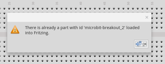
For the part with the same name, I believe the message is something about the same id. Once loaded, Fritzing tracks parts by an internal id string. Duplicates are not allowed. It can happen that a loaded part gets saved in the local parts area, but is not visible in any of the bins.

It might be possible to locate the part using the search function in the “Parts” window. If you can find it that way, drag it into a temporary sketch window, right click it there, and select “Add to bin” from the context menu. With it visible in the bin, it can then be deleted. Close Fritzing, and save changes to the parts library and bin, if prompted. You do not need to save the temporary sketch file.

If that does not work, the locally stored files can be manually deleted. The folders they are in is different depending on the operating system. The top folder of interest is:

Windows

c:\Users\username\My Documents\Fritzing

Mac

/Users/username/Documents/Fritzing/parts

Linux

~/Documents/Fritzing/parts

Inside that folder is a user folder that contains the loaded part definition files, and an svg folder that also contains a user folder, which in turn contains additional folders, one per view. So, starting from that top folder above, a full part will have files:

user/file.fzp
svg/user/breadboard/file.svg
svg/user/icon/file.svg
svg/user/pcb/file.svg
svg/user/schematic/file.svg

“file” can be different in each folder. The fzp file contains references that tell what the other files are. Not all of those files have to exist. Some parts do not include image files for some views.

The main file to delete is the fzp file. That is what contains the id that Fritzing is complaining about. The related files should be deleted for general cleanup, but I do not think Fritzing actually cares. If a new part uses the same image file name, I think they will just be overwritten. I have not tested that though.

There is also a bins folder (on linux it is ~/Documents/Fritzing/bins) that contains local part related information. Specifically, for any locally defined bins. The my_parts.fzb file could need some cleanup with a text editor when manually deleting parts. However, if the part was not visible in the “Mine” bin, it should be correct already. More complex cleanup situations might include needing to edit that file to delete instance entries for files that do not exist.

Excellent! Many thanks @Old_Grey and @microMerlin for the help removing the old part.
All looks good now.

My next step will be to learn to edit parts :slight_smile:

And thanks @vanepp for the new part, it looks great!

Hi there,
This is fantastic. I’m in a similar position with a similar but different Kitronik Break out board for the Discovery kit. I have just created a first diagram to support my tutorials but it would be great to be able to get a part for this bread board breakout thing.

Any help would be really appreciated.

Someone might come along and do it, but it might take a while.

If you want to watch this vid, you might be able to make it yourself.

Should be easy enough to do. There is a pdf with the necessary information in the linked web page. It will probably be a few days til I post it though. Unless you need a lot of parts it likely isn’t worth trying to learn to make parts, as it is fairly complex for a one of it is easier for one of us to make it for you.

Peter

Hi there,

This great news. It’s not a desperate rush. I can put a placeholder in while I work on it.

It’s for a free course on physical computing that I’m working on -
https://en.flossmanuals.net/intro-to-physical-computing/_full/
but I’ll definitely contact Kitronik to let them know about these parts too, as this isn’t something they seemingly have someone on their team to do.

Thanks
Mick

It was pretty easy, just removed unused pins and renumbered. The microbit looks a bit odd in breadboard because of the smaller space though :slight_smile:

microbit-breakout-kitronik-5664.fzpz (21.8 KB)

Peter