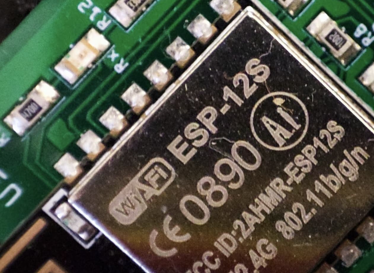
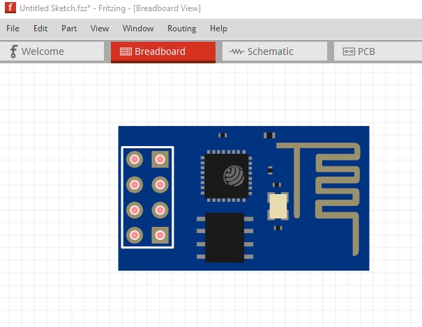
Luckily I’ve found the ESP8266 part which I’ve used in a PCB design before has the exact same castellation arrangement, this reflowed perfectly on previous PCBs so I will use that part as a starting point and modify it.
So in fritzing the two parts compared, not a million miles different.
Which ESP8266 Fritzing part is that? I’m interested in looking at what is different about it (because I still believe the problem is in the PCBWay viewer not the part.) The pins are a fair bit smaller which can be a problem though.
All other parts are absolutely fine at JLCPCB or PCBWay viewers so I can’t believe they would just get one wrong out of all of them, after all they make PCBs, that is all they do.
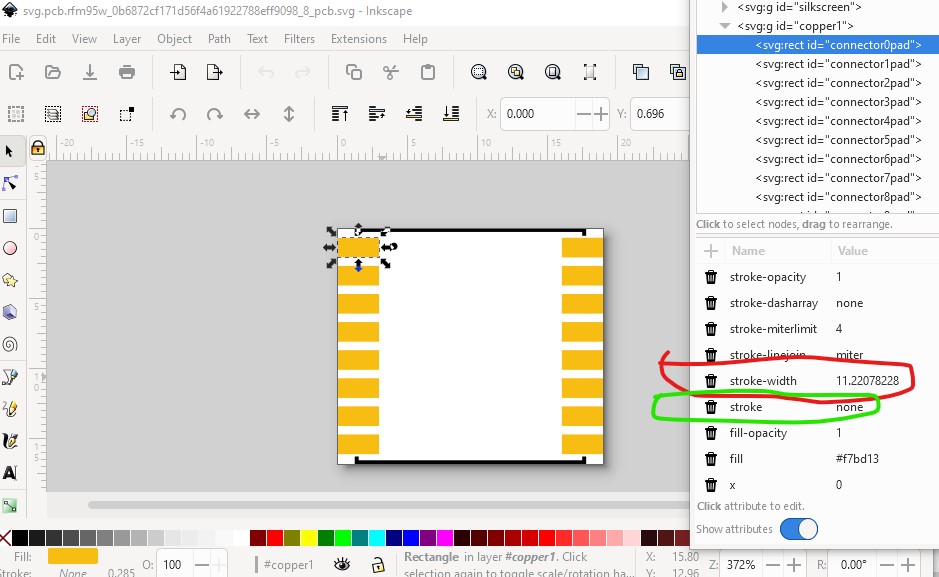
I have not seen any of the part information, but am wondering if the problem is as simple as having a non-zero stroke width for the pads in the part. Pads are not like THT. They do not need, and (I think) should not have a stroke width.
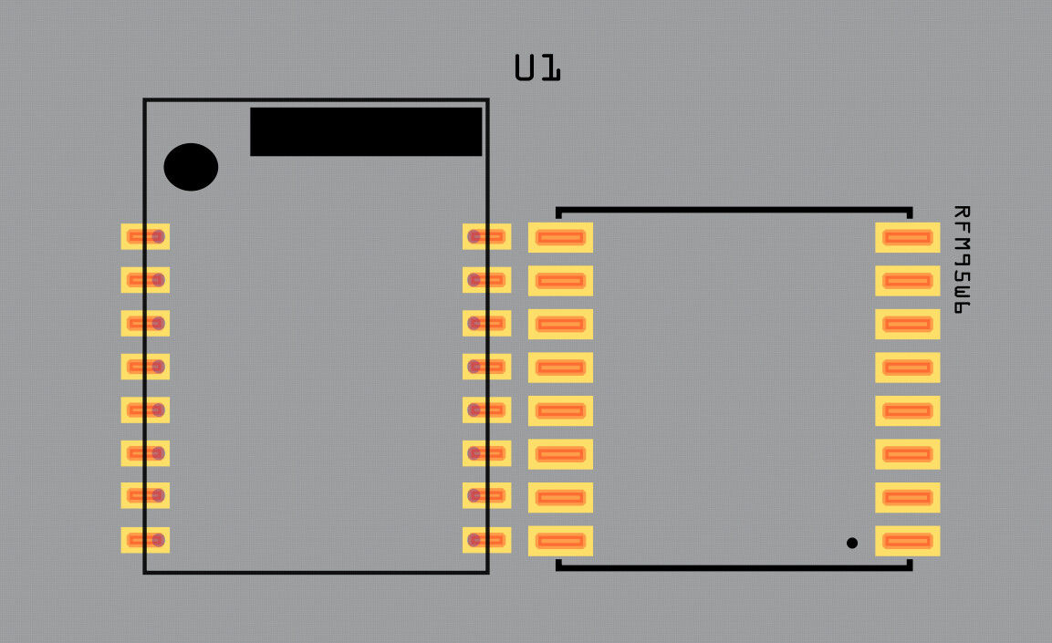
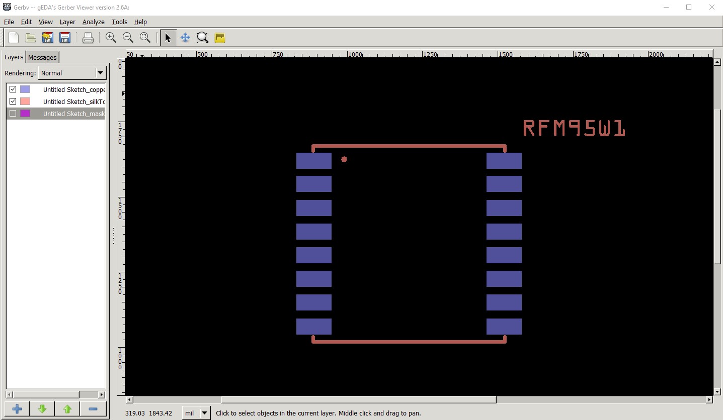
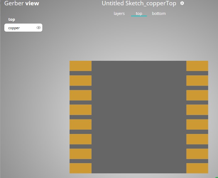
And I believe (without proof mind you!) that this board will work fine too. The copper layer (which is what counts) appears to be correct. Their viewer looks to be rendering the mask layer (and I doubt they made the viewer) over top of the copper layer and making it wider. I agree that it is very unlikely that the board would come out wrong and not be noticed but an error in the online viewer is another matter.
Good thought! They have a stroke-width, but with stroke is set to none which should cancel that, but I will experiment with that as well and see if that is the problem here. As I say I think the problem is in the online gerber viewer not the part but I could be wrong. It is easy enough to kill the stroke-width in a test part and see if the fixes the problem.
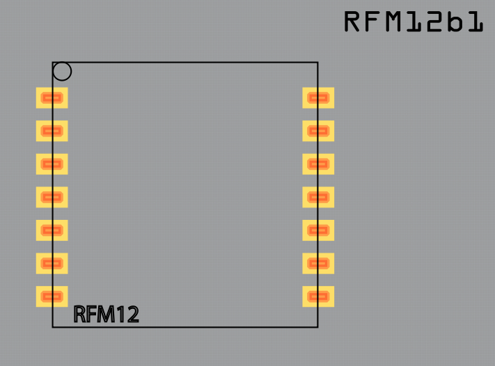
This was your copper layer from your own viewer, those pads are too big even there and don’t match the PCB view in Fritzing. For example in the PCB designer there is enough room to root traces between the pads, not so on that view of the copper pads, just look at the lack of space between them compared to part shown on the PCB designer in Fritzing. What you see should be what you get.
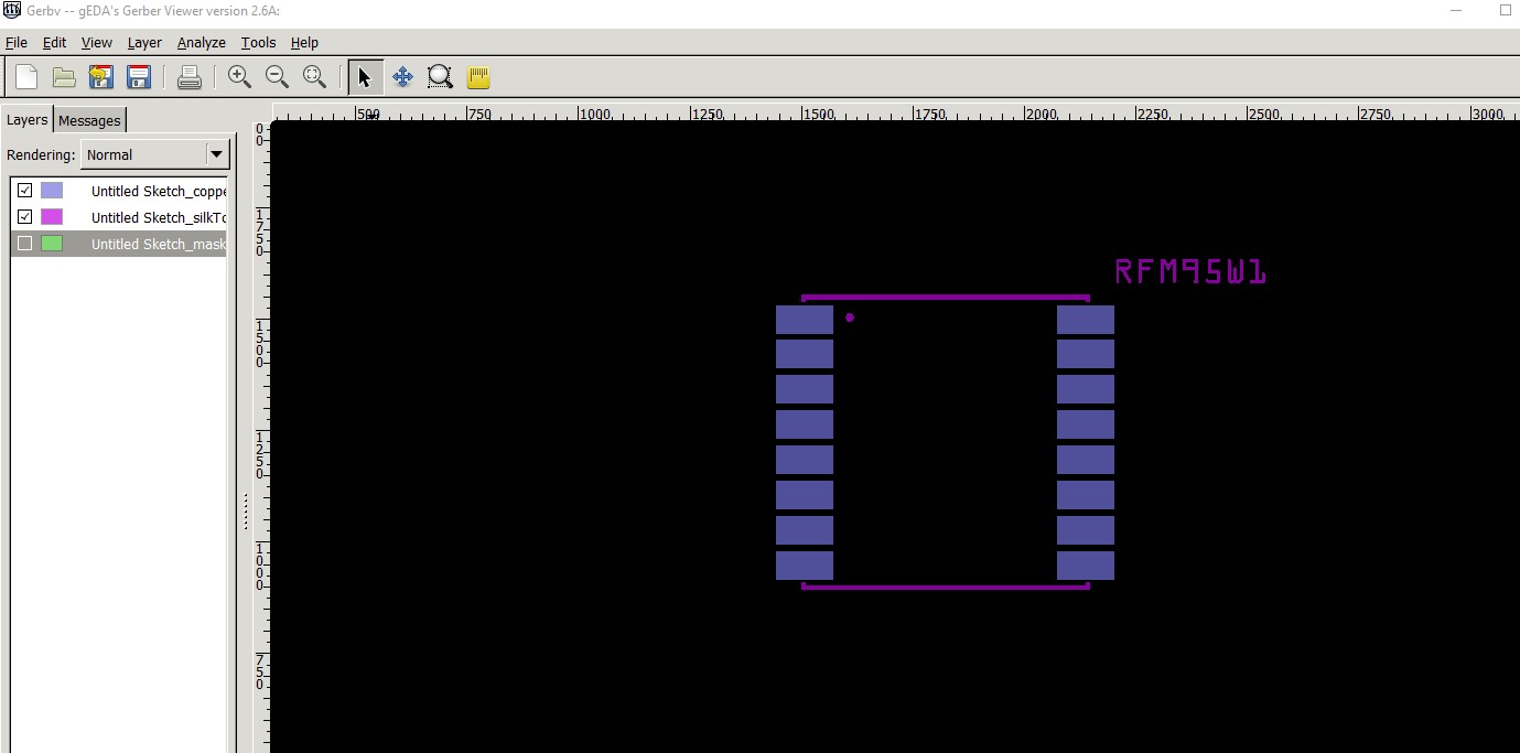
Variant 7 will be a different part (either in your system or in core parts) which may not be the same here. However @microMerlin appears to have called it, the stroke-width being non zero is affecting the pad size (which appears to be a bug in gerber processing as stroke is none.)
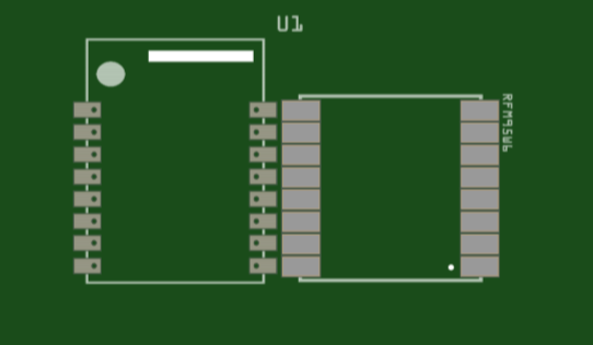
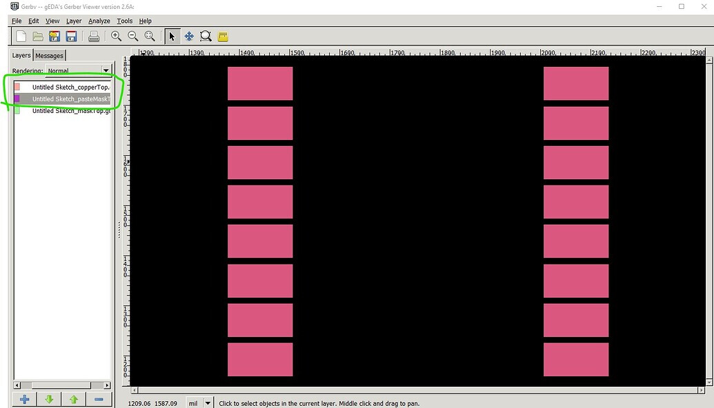
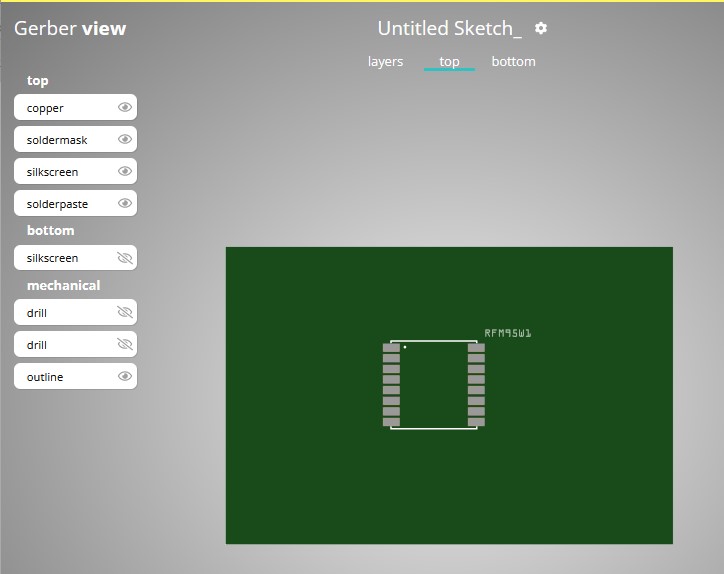
The gerber output from a part with the stroke-width set to 0 (with stroke still none)
Indeed that is looking better. I will play safe and modify the ESP8266 part as that looks better still and I know that land pattern works with no problems. The pads still look larger than I would expect on this RM95W part with less of a gap in between. With the ESP8266 land pattern there was room to route a trace between them, so its a bit more flexible as well.
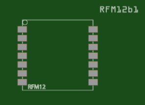
Has that been there all the time! Not sure if I’ve acquired this part or it was always there, but I just found a RFM12b1 from HopeRF in my parts in Fritzing, looks like a good candidate as well with the same layout.
Like buses, wait for ages then 3 arrive at one, spoilt for choice now.
Edit, it has fewer pads, but of course can be edited.