Now the roboRIO part. For this one I switched to a part that I made a couple of years ago that had the schematic already. The delay in posting this was caused by cleaning up a 2+ year old part (I knew a lot less about part making at that point) but it is now done and I have some improved tools for cleaning up parts because this was to complex to do manually in any reasonable amount of time.
roboRIO.fzpz (221.6 KB)
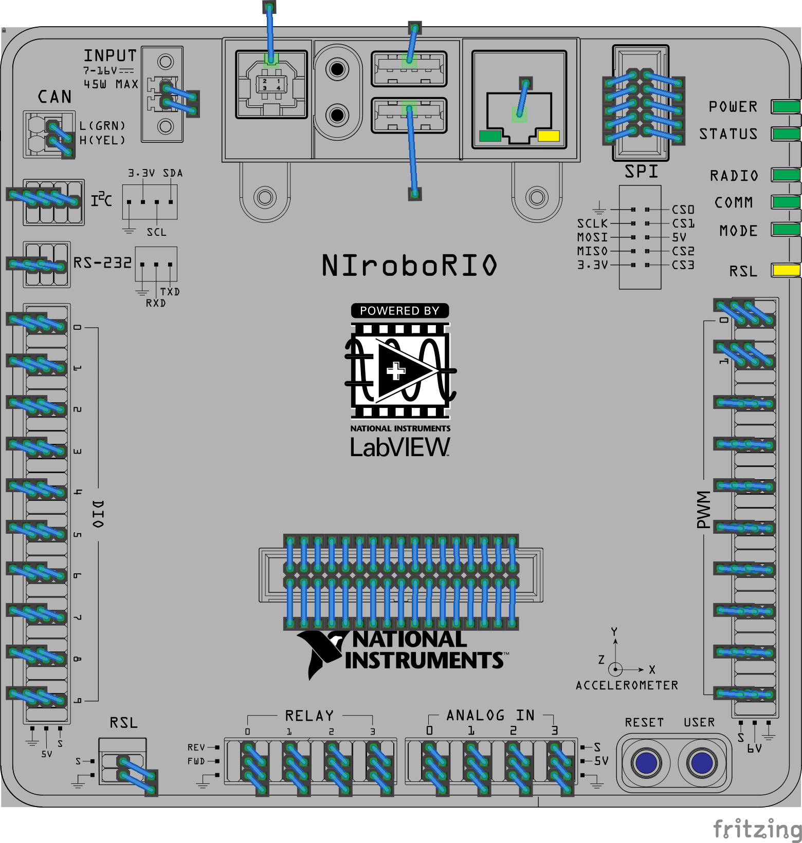
breadboard
schematic
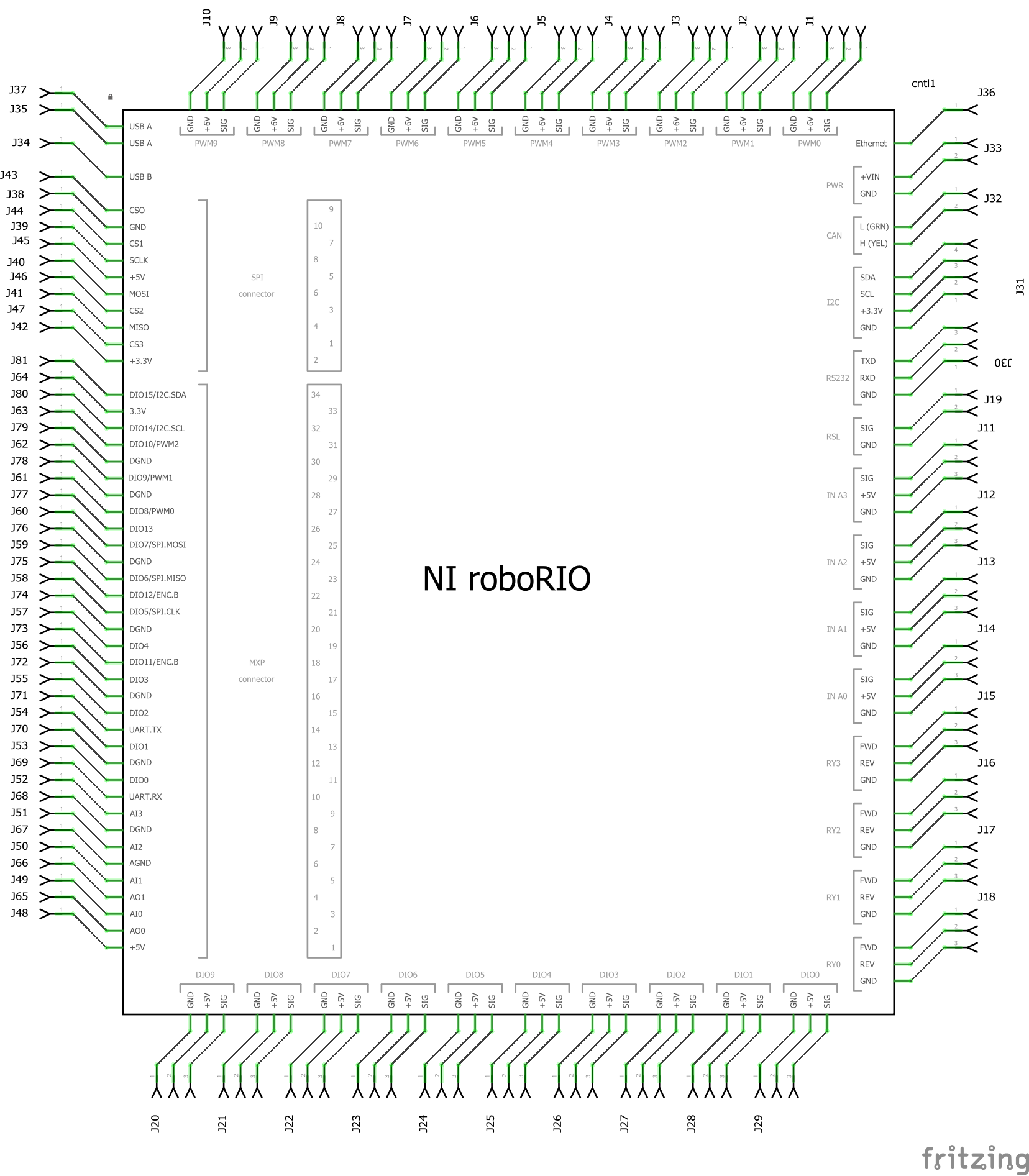
The power and grounds have been bused, one thing I’m not sure of is if the alternate connections on the MXP connector for SPI and I2C are shared with the associated pins on the dedicated SPI and I2C connectors. I have assumed not (the manual doesn’t say and I don’t have a unit to test). If they are common, then additional bus elements need to be added to indicate that.