Now the PDP (Power Dirstribution Panel part. This one has substantial changes as the pin numbering in breadboard was an odd sequence and schematic was non existent (due to not enough connectors defined) and thus needs a good check. I don’t have a unit so am going by the documentation and the original part. Again PCB view is disabled as this isn’t useful on a PCB.
PDP-orig.fzpz (33.4 KB)
PDP.fzpz (44.9 KB)
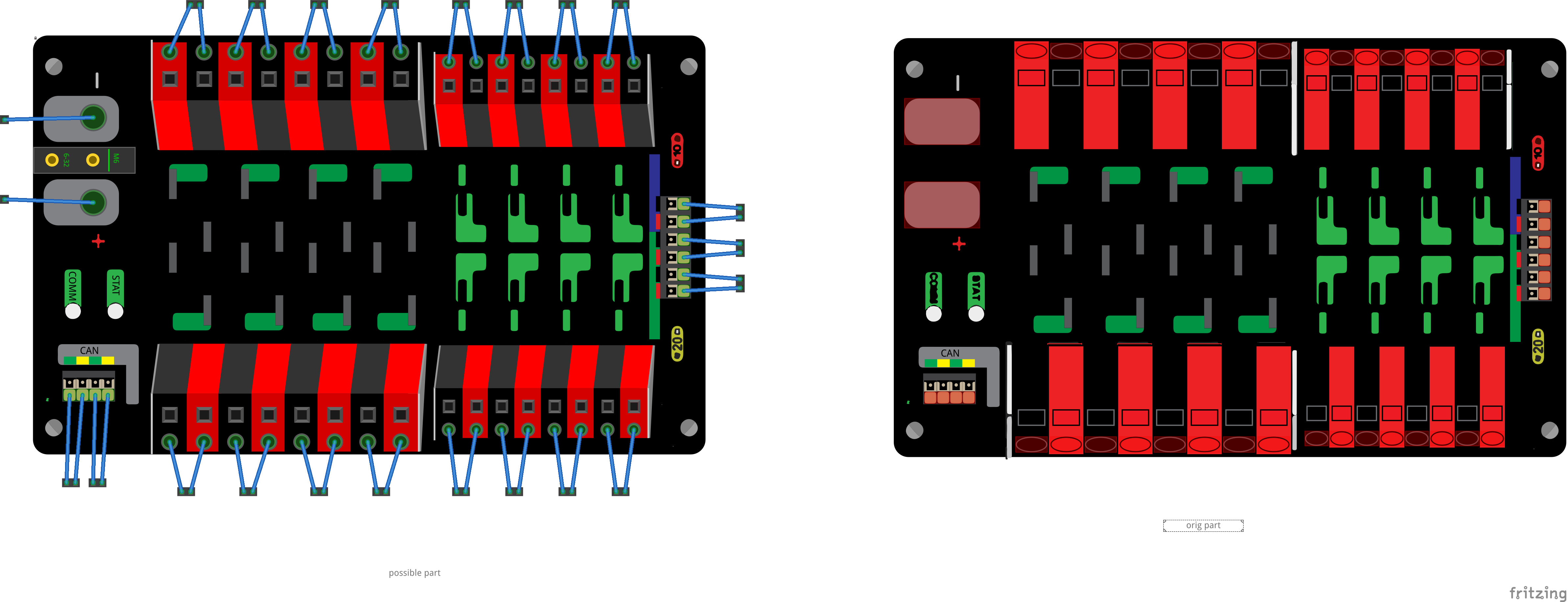
breadboard:
The usual rescale and clean up xml, in addition this time a complete renumber of the pins starting with 0 at channel 0 - and proceeding in order around the perimeter. As well all the grounds are bused together (click on any ground and all the rest will light yellow) as do CAN high and CAN low. I copied the breadboard of one of the screw terminals to give a bit more life like representation of the power pins.
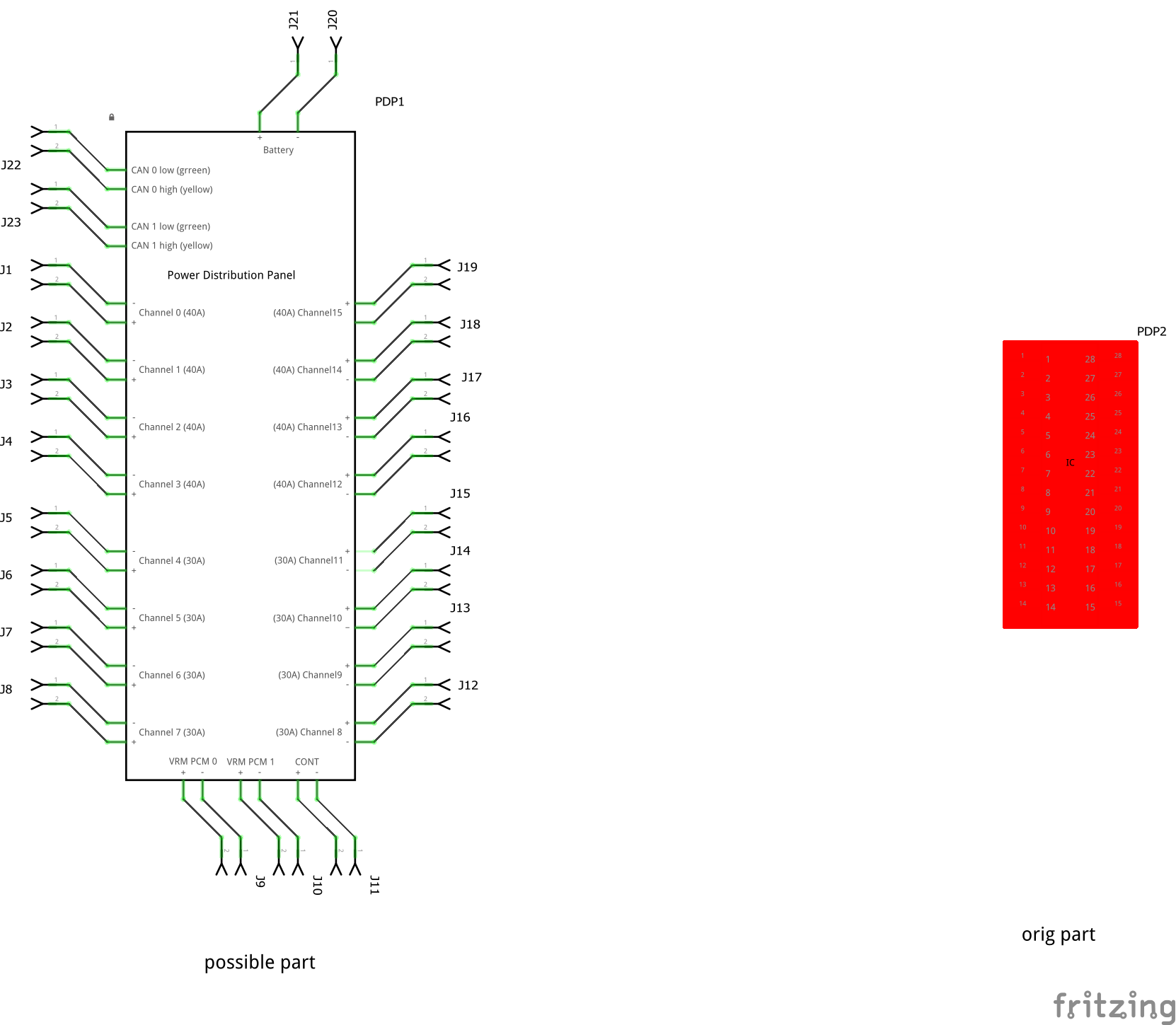
Schematic
Created as the original doesn’t render as it is a 36 pin IC but there are 44 pins which is what causes the red square in schematic.
Peter