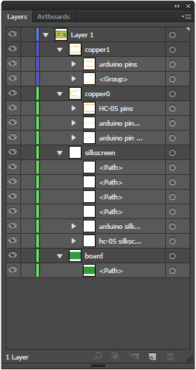
silkscreen
copper1
copper0 (child of copper1)
pins (children of copper0)
The pads will be copied to both sides of the board automatically. Silkscreen on the top aids in selection in pcb view (it prefers to select silkscreen if it is on the bottom).
I usually take it that copper1 is pads on top and copper0 is pads on bottom, and because copper0 is in copper1 you get pads top and bottom. If you only want one side use the copper# and delete the other and ignore the warning like we get with all top sided SMD stuff.
I do remember someone say a long time ago that they don’t necessarily have to be 1 top and 0 bottom, but I don’t know the details. Maybe when you drag a part on a PCB from the top they are that order, but if you flip the PCB to “View from Below” and drag a part on it’s reversed.
That is correct, this came up a while ago when someone wanted an edge connector. We ended up making a part that is one side of the edge connector and putting one on the top of the board in the sketch and another (with the side of the board swapped in inspector) on the bottom of the board to create the edge connector but I couldn’t see a way to do it with a single part. Of course in that case I needed to be able to get the pads through hole (achieved by vias and hand routing) so if you just want SMD pads Old_Grey’s suggestion may work.
Okay - thanks guys. I will try to make one SVG file with top layer components and then a second one for the bottom layer.
One more question that I have is - how do you align the parts on the grid properly? It seems to always snap to the grid. Is there a way to turn the snap option off? Or to resize the grid?
EDIT: Nevermind I found the turn off snap to grid option under the “View” tab
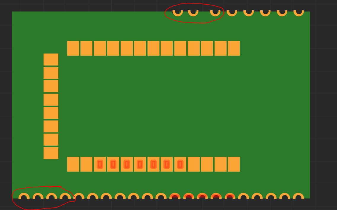
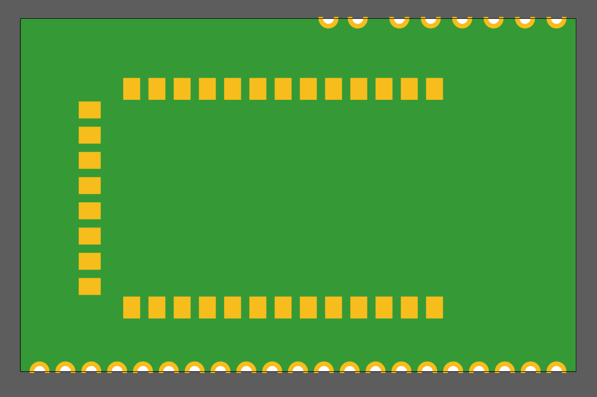
EDIT2: I now tried to add only one side of the copper layer on a custom PCB (also from an SVG file).
When I made these 2 SVG files they were perfectly aligned. But now in Fritzing it seems that the connector pins on the sides are not aligned anymore. See below an image. Any ideas why this is happening? And any workarounds?
Illustrator uses a different pixel count per mm then other scalable graphics programs like Inkscape and that could be your issue. Hopefully someone that understands better can explain it and also explain how to fix it.
I suspect @sublimeartistry is correct, you have likely hit the scaling issue (it has bitten me enough that the first thing I do when modifying a part is check and set the scale). If your document it defined in px (and no units is px too ) then Fritzing guesses which DPI is in use, old illustrator used 72dpi, Inkscape used to be 90dpi and I think that CSS may have been too, Ink and CSS are now using 96dpi. The fix is define the doc size in inches or mm rather than px (and preferably have the scaling at 10 to 1 so 1px equals 1 thou). From an Inkscape svg (it should be standard so Illustrator should be similar I expect)
edit: forgot that the forum takes xml as markup and you have to screw with preformatting …
(you don’t want no units or px which will cause Fritzing to guess) and
viewBox=“0 0 2559.051 1000.0092”
at 100 * the height / width (if in inches) gives a scale
of 1px = 1thou. This is as recommended in the parts file format document on github which also documents what Fritzing wants in the svg files and the fzp file:
I’m not sure if this is right, but Are you adding both part layers to FZ from View from Above, or 1 from View from Above and 1 from View from Below. Each part has a pages size, and I think it’s the pages size border that it snaps to.
Yes, the bottom one defines the scale as 1 px = 1 thousandth of an inch which is the standard called for in the Fritzing part file format document on github. However that shouldn’t be the cause of the pad problem as the 1:1 scale in your first example should work the same (as long as Fritzing doen’t make a mistake about the dpi value which it usually doesn’t) and if it did make that mistake the scale of the pads would be incorrect not the shape.
Yes, if you are changing an existing drawing you need to do it in the svg editor and let it rescale the drawing. Assuming Inkscape what I do is first ungroup everything (to get rid of all transforms) then edit->select all and file–>document properties->resize selected to page. I usually need to change preferences to enable Behaviour->Transforms->scale stroke width (which I normally want disabled so it leaves stroke width alone if I stretch a line). Then record the x y width height from the tool bar in px. Now in document properties change the scale window from whatever it is (probably around 1) to 10.41667 and click on the drawing. The drawing will shrink to a small size like in Fritzing. So edit select all again (as it also unselects) and using the tool bar set the x y (0 0) and width height back to what they were originally and Ink will rescale the drawing to the correct size. I usually use xml editor to set the view box to the exact numbers at this point as Ink gets it close but not quite exact usually. Now if you save the drawing as plain svg your scale should be right in Fritzing. If as I usually do you forget to enable stroke-width scaling you will get very thin lines in the document as the stroke widths haven’t scaled.
Unfortunatly, no I’ve never used Illustrator. I expect it would be in a similar place since it affects the formatting for the entire document. Hopefully someone familiar with Illustrator can chime in with how to do it.
What goes wrong? It may be easiest to upload the svg (you may need to rename it to fzpz as sometimes the forum doesn’t like rendering svgs) and I’ll keep a log of what I have to do to rescale it.