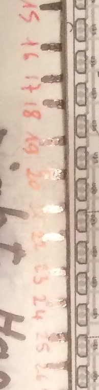
it is more difficult for the right hand because presumably a magnet all three rods will be fixed on the small black rectangle. the others on a rod except the first rod on the extreme left in the photo that has no sensor or magnet, no acoustic sound! no spit
OK here is a revised left hand layout, now I’ll have a look at the right. I managed to figure a way to import the black dots that I assume are the magnets in to the layout and moved the sensors to match the center of them.
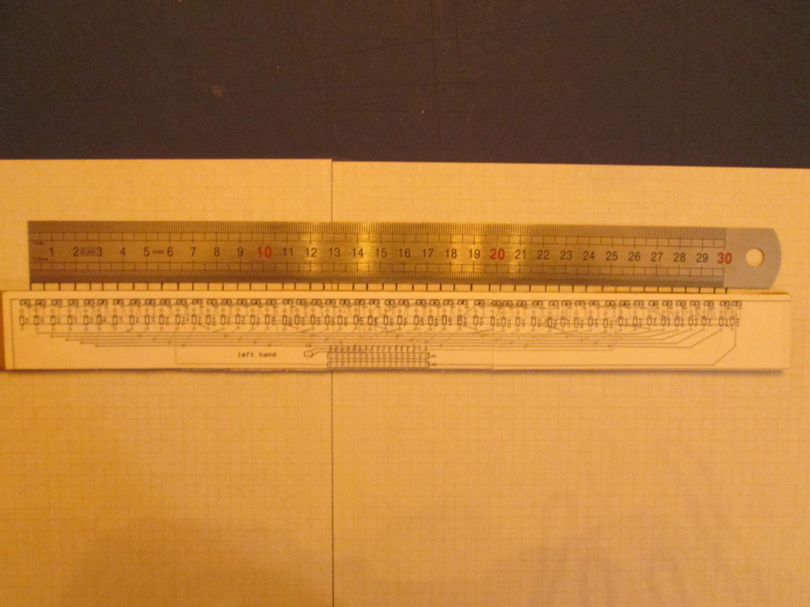
accordion-left-hand-Sketch.fzz (182.3 KB)
Peter
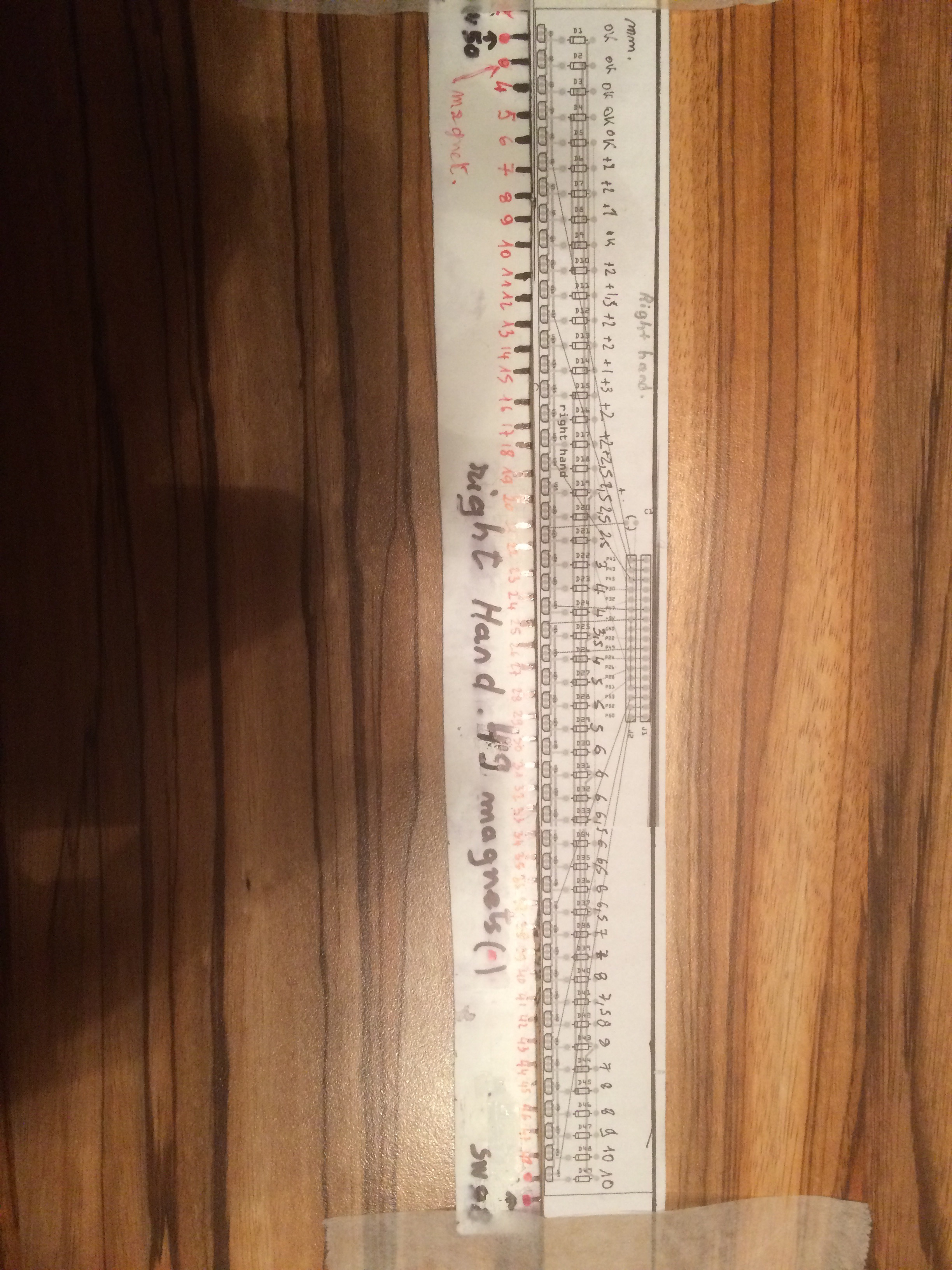
Could I get another copy of this with dark marks where the magnets / sensors should go and the ruler please? I import the jpeg in to Inkscape then scale it until the ruler is at real life and them move rectangles to where the magnet is marked to position the sensor in pcb. The current picture blurs to much to be useful when the black dots became white:
original jpeg:
The same image after import to Inkscape:

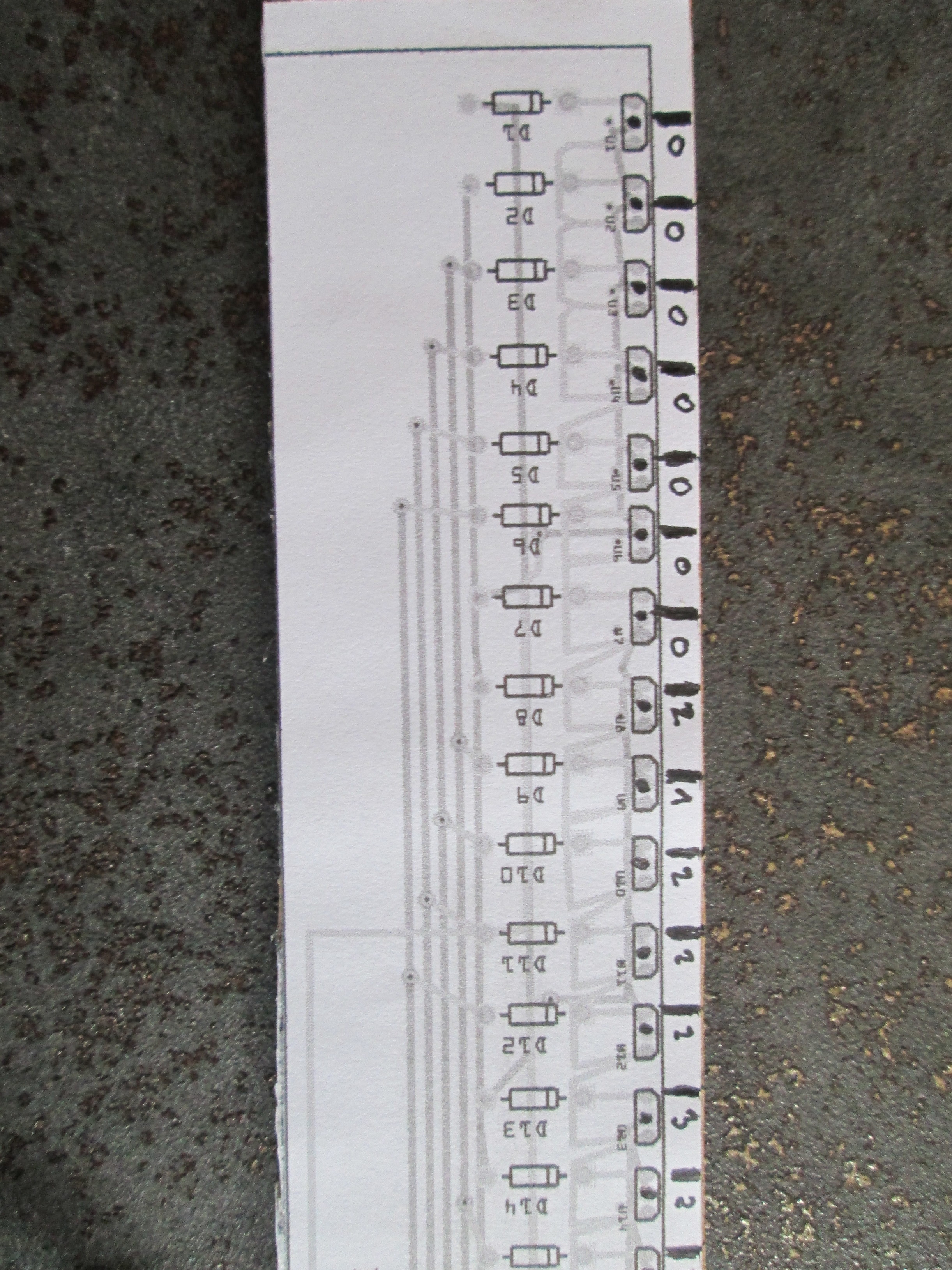
The black line is moved to the center of the magnet position and then the black rectangle is centered on the line. Then the black rectangles are imported in to Fritzing to position the sensors.
Peter
OK here is a copy of the right hand board with the sensors moved to your list of offsets above. If you need changes, you can just make a clear mark where you want the sensor and I can import the jpeg and scale it to move the sensor to the position you choose without needing to measure it.
accordion-right-hand-Sketch.fzz (171.5 KB)
Peter
I controlled the right hand is great!
just + 1 mm for the sensor and diode D9. I print my left hand and I control. good job peter!
Just to be sure I’m clear, the black mark between the sensor and the ruler is where the sensor should move to?
Edit:
Here is a new copy of the right hand board fully routed (still needs some of the traces straightened but other wise ready to go). You should verify the sensor is in the correct direction when installed according to the diagram (i.e. with the beveled edges outwards) to make sure we have the orientation correct.
accordion-right-hand-Sketch.fzz (182.3 KB)
Peter
yes the sensor must be positioned in front of the black mark! thank you for the new diagram I will check tomorrow good evening
Hello peter,
Thank you for the last circuit board for the left hand.
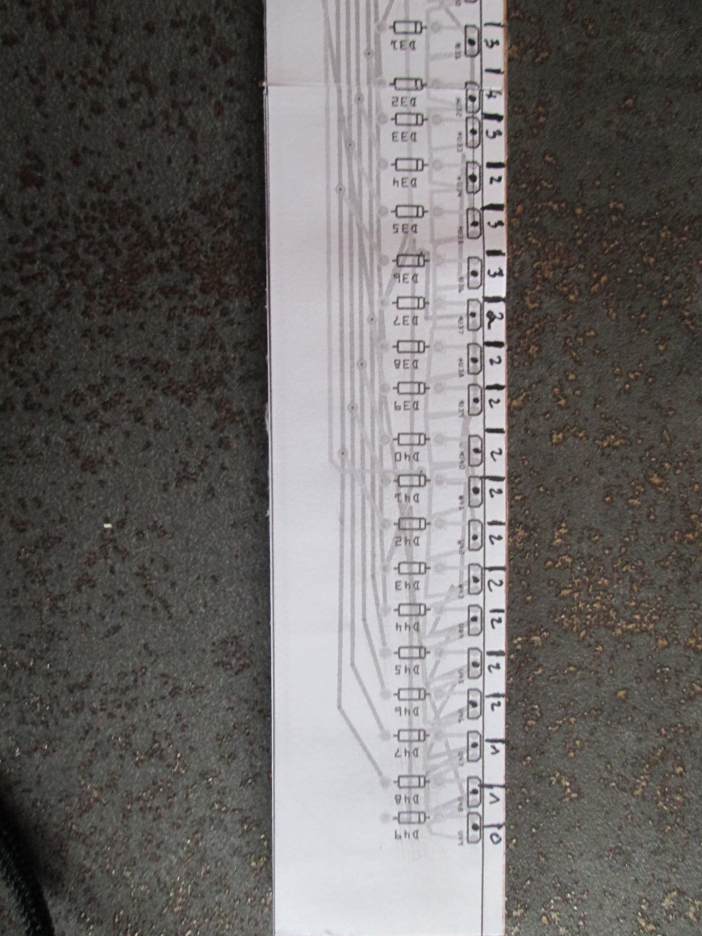
This morning I positioned the penultimate circuit board of the right hand ( before rectifying the sensor d9) inside the accordion. There are two other sensors to slightly modify the D17 + 1mm and the D 21 + 1mm sorry. My apologies but it is very difficult the bars are not perpendicular exactly. It is already very well that there is very little difference!
I will print the last painting of the left hand sent this morning.
I will wait to print the last circuit boardof the right hand after that you made the last two rectificatifs (D 17 and D 21) Thank you for all it’s great!
Can you give me a price order and tell me if the diodes will be soldered on the PCB? philippe
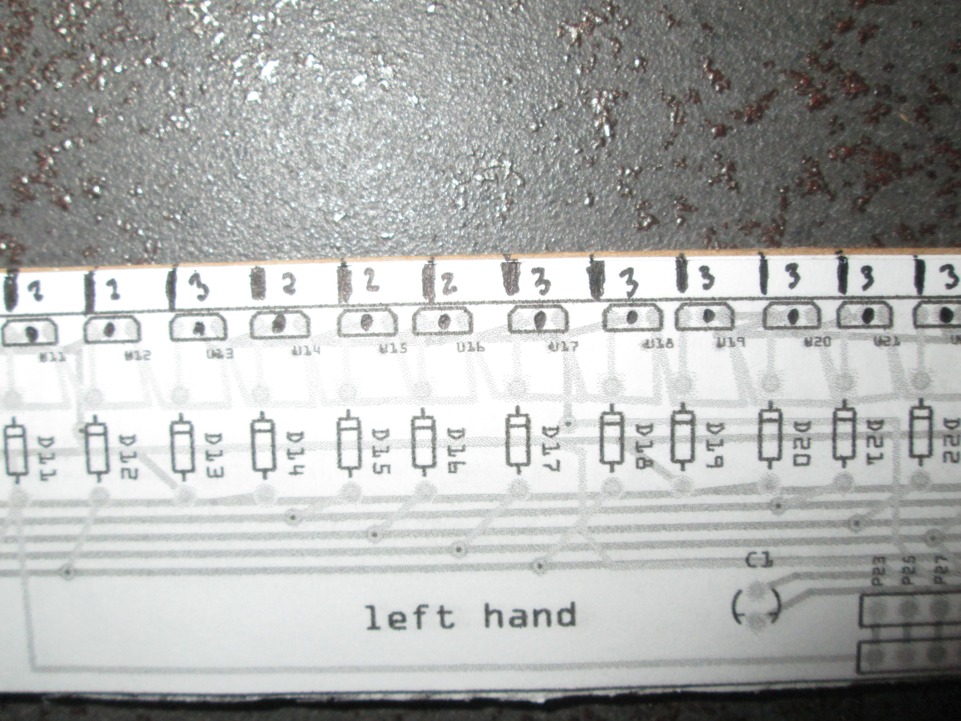
errors for the left hand. I positioned the circuit board inside the accordion and made photos by annotating the gap in mm there are 4 photos for all 49 sensors I hope it will go!

The diodes won’t be soldered in (or installed) all you will get are the boards with the holes drilled, you need to do the assembly. As to a price, you need to select a company and get a quote once the boards are finished. There are lots of choices starting with Aisler, who are the fab for Fritzing in Germany. They feed back a portion of their fee to Fritzing development and check the board over before making it. They are fairly expensive compared to the discount pcb makers, but the discount houses don’t check anything and just produce whatever you order. I havrn’t made boards in many years (and used a local firm here the last time i did), but elcrow in China
https://www.elecrow.com/ was recommended to me and osh park is another that people have used https://oshpark.com/. You could get a quote from all three and choose the one you like best. That said here are current versions of both boards with the latest corrections in place. I added 4 2.2mm holes on the end of the connector on the right hand board so you could if you wish attach a piece of plastic to hold a dupont connector in place. I’ll do the same on the left when I fix up its routing.
accordion-right-hand-Sketch.fzz (182.8 KB)
accordion-left-hand-Sketch.fzz (182.3 KB)
edit: On the left U24 and U25 are probably in the wrong place. U24 I don’t think got moved and U25 may have been moved wrong.
Peter
Good evening Peter
I will look tomorrow your two diagrams thank you good evening
hello peter, it’s perfect for the right hand!
Can you add holes of 2. 2 mm to 230 mm and 300 mm. the total length is 360 mm for the right hand 2.75 mm - 305 mm - 2.75 mm. Can reduce the width to 25 mm? I look at this afternoon my left hand. Thank you for all philippe
Hello again, it’s almost perfect for the left hand
u 17 + 1mm, U 21 + 1mm, U 24 + 1mm, U 29 + 1mm. I think we can not do better! nice work thank you Peter
OK I’ll make these changes and hopefully finish up the routing and repost.
Peter
OK a new pair. The right side has been lengthened to 360mm and narrowed to 26.5mm (as much as I could without moving traces). I can probably move the traces closer together to get the extra 1.5 mm if needed. I added two 2.2mm holes at 230mm and 300mm aligned with the holes on the connectors in y. Easy to move if needed. The routing is all done and the right should be complete now. On the left I have made the requested sensor poition changes and will continue with the routing while you check the changes.
accordion-right-hand-Sketch.fzz (184.9 KB)
accordion-left-hand-Sketch.fzz (149.1 KB)
Peter
thank you very much for your work I will look tomorrow philippe
I just finished the routing on the left hand board, and indeed smaller traces let me fit it in 25mm (and so the right can be done the same). However it is late here, so I’ll fix them up tomorrow and repost them (I imagine that will be afternoon your time).
Peter
Good evening Peter, it’s almost perfect for the left hand just move U 8 + 1 mm.
I will also like holes and I will also give you holes for the fixings of the two printed circuits. I will also check the connections and pinning with regard to the scarff tom sketch. I would like to know which section of wire (28 awg?)i have to use with the duponts pins. ? thank you
https://www.amazon.fr/Kamtop-Sertissage-Sertisseuse-Connecteurs-0-1-1-0mm²/dp/B078K9DT69/ref=pd_sbs_60_4/260-0342006-7689404?_encoding=UTF8&pd_rd_i=B078K9DT69&pd_rd_r= 5917018a-4997-11e9-A334-c3126910e770 & pd_rd_w aW2YH = & = pd_rd_wg AOXDe & pf_rd_p = ce0bf35d-908D-4dcb-a083-3a6e21394b79 & pf_rd_r = 67TNZ9DEYG2R5QDGJTE7 & psc = 1 & refRID = 67TNZ9DEYG2R5QDGJTE7