côté main droite du clavier à l’arrière sortiront broche midi , usb , push buttons et à l’intérieur du soufflet only les nappes informatiques.
les connections de la carte arduino sont très délicates ne peut on pas trouver un brochage plus solide ?
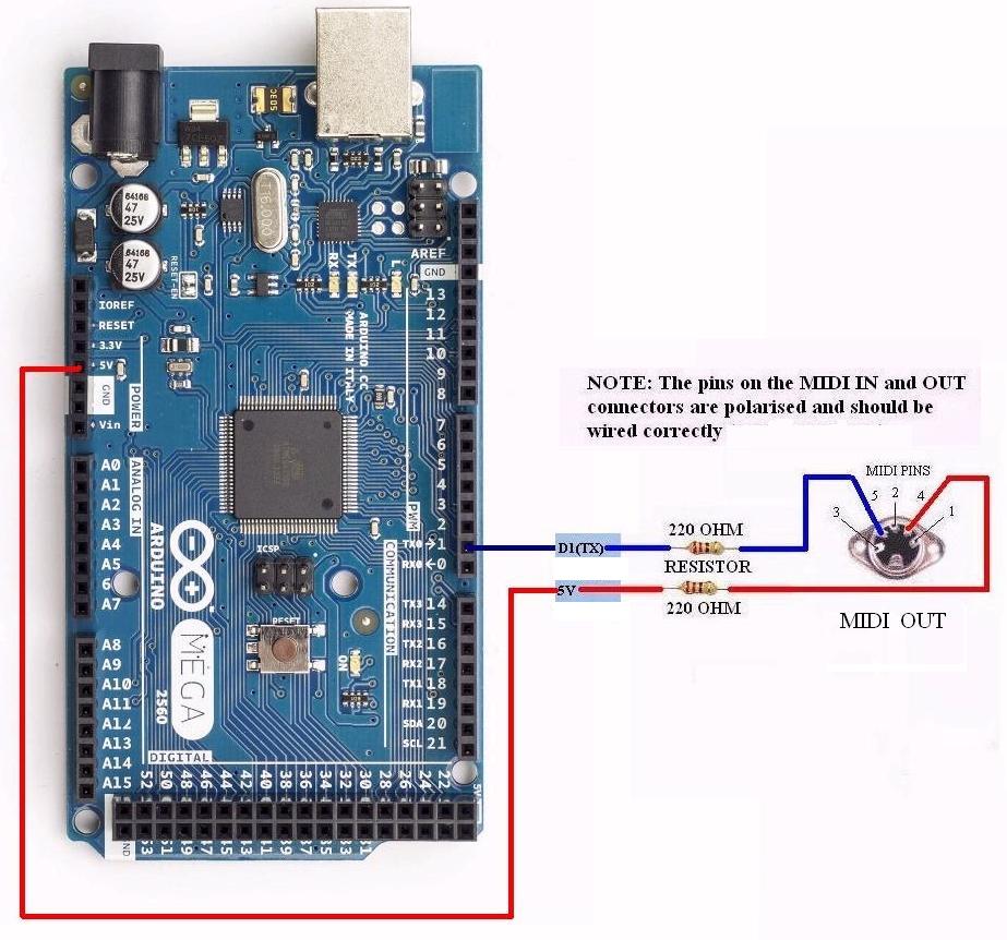
j’aimerai également installer sur ma carte arduino at mega 2560 un capteur de pression bmp 180 mais il faudra modifier mon IDE . Je ne connais pas le langage de programmation arduino !!! Je possède l’ide que m’ a transmis tom Scarff : http://midikits.net/
I have the IDE from my arduino card
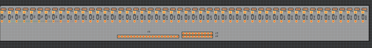
OK, I’ve scaled the sensors to be evenly spread across 300mm in this sketch. I’d suggest that you print the pcb section of this sketch at 1 to 1 scale and try it where the final board will go and see if it will work with the sensors laid out like this or if we need to make changes (at this point with no routing changes are fairly easy). As well I added a 20 pin staight header (for header or more likely wires) and a dual row header for a ribbon cable connection if you choose. Again check that their position will let you get the wires out to where they need to go as again it is easy to move them now but harder later. As to the pins on the Arduino it is possible, but not necessarily easy to unsolder the header pins from the board and solder wires in their place with no headers. That is a stronger connection. I don’t know if anyone sells Megas without the headers soldered on (that would be the easy way to solve this problem.)
edit forgot to upload the sketch …
accordion-Sketch.fzz (67.5 KB)
Peter
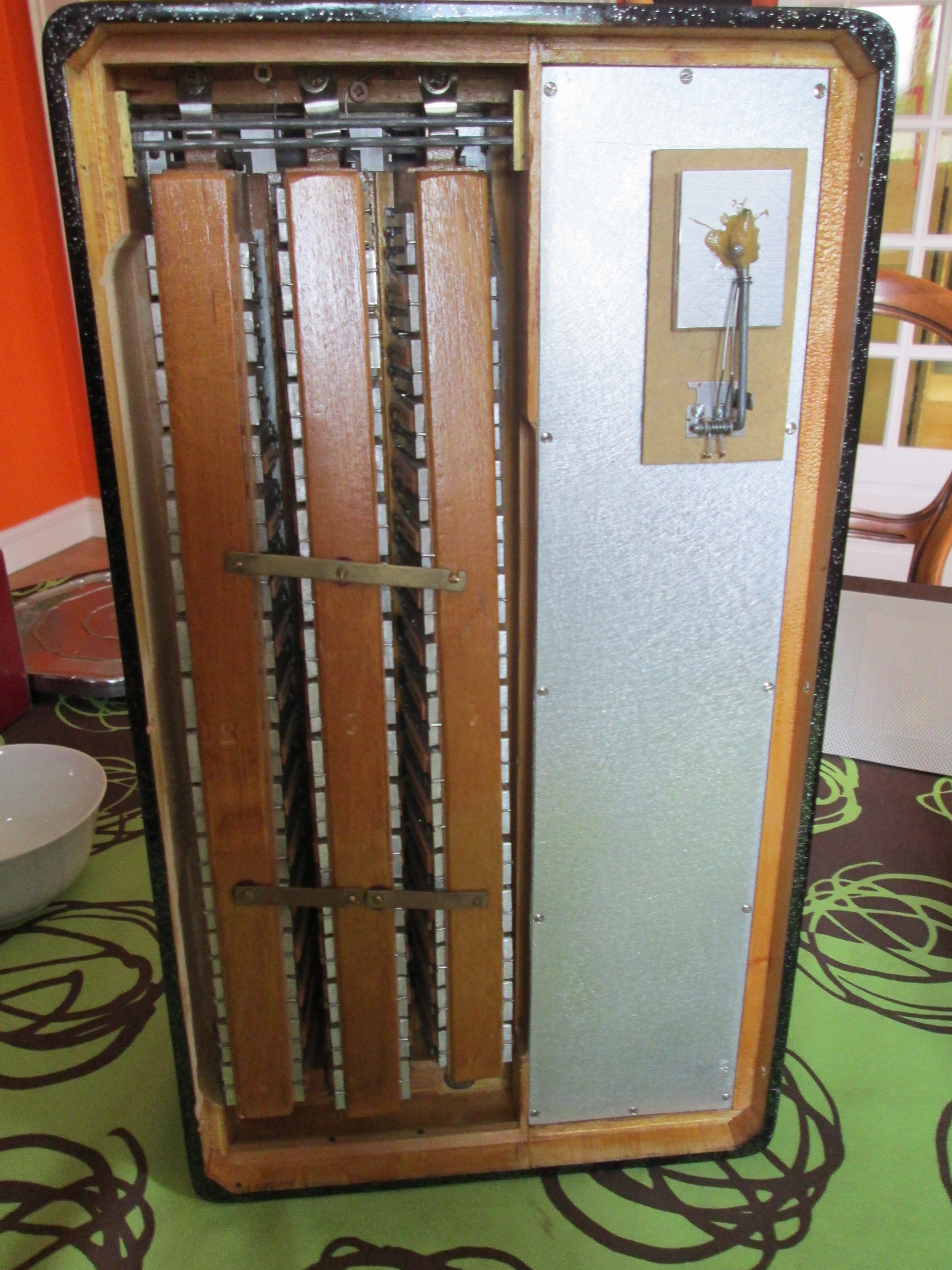
la carte arduino sera fixée côté main gauche sur les sommiers avec si possible le capteur de pression BMP 180 et la nappe ira côté main droite à l’intérieur du soufflet et côté main gauche en réalisant une ouvertture ,dans la partie gris métal
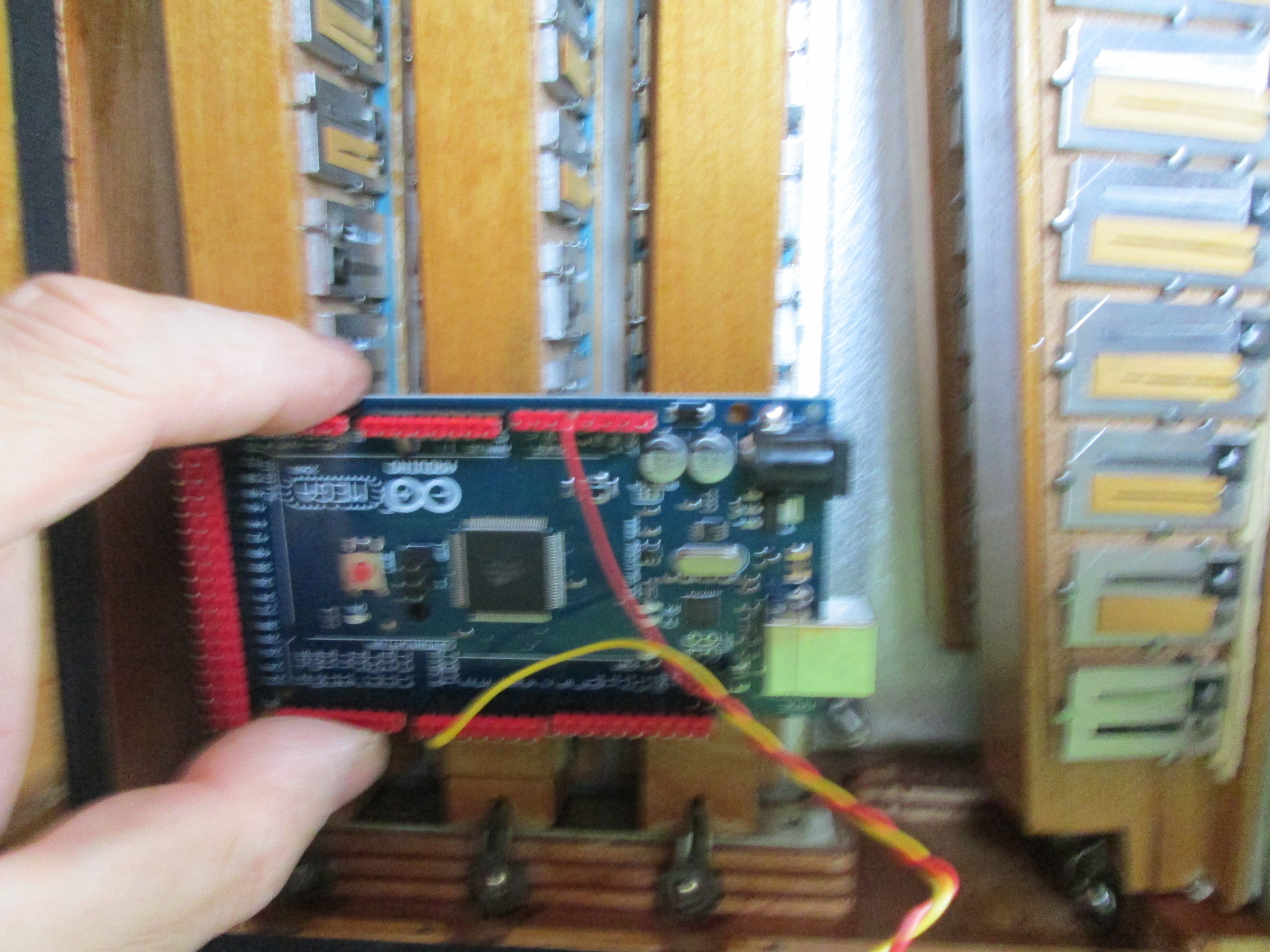
For the left hand circuit board , its good en high because i make a hole en high like on the picture
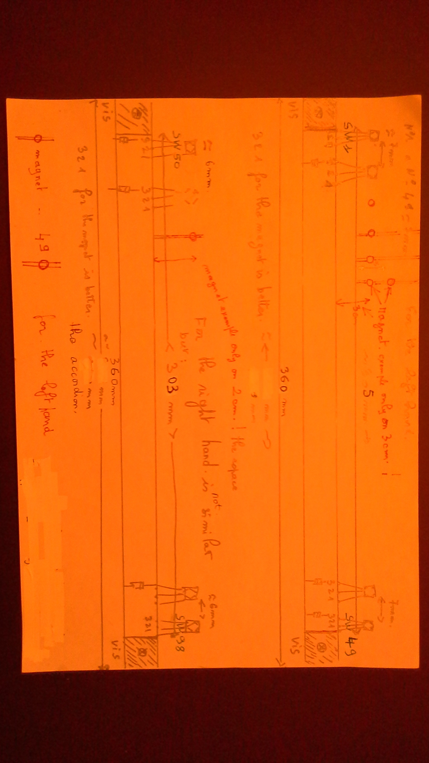
Oui les 2 tableaux peuvent avoir la même taille : 360 mm . C’est le capteur n° 50 qui ne fonctionne pas sur la main droite car il n’est pas déclaré sur le programme de la carte arduino ( IDE ). sur le schéma de tom scarff " right hand swichtes " et dans ces commentaires il dit : SW 98 / D 98 vers 50 on pourrait imaginer : SW 99/ D99 vers 50 car i think que le programme peut reconnaitre la note midi après pour faire la même carte sur 49 capteurs pour les deux cartes. Attention l’espace entre les aimants est de 7 mm à gauche et de 6 mm à droite il sont aussi donc un peu plus proche à droite. Oui les capteurs fonctionnent mieux avec l’aimant lorsque le capteur présente 3 2 1 sur le schéma , le capteur à effet hall est plus sensible .Non je ne veux pas de trou sur les extémitées de la carte . je vais regarder pour les connecteurs dupont , je connais mais il faut vraiment que cela soit serti , il faut que je puisse passer un cable de la caisse droite et un cable de la caisse gauche dans un trou de diamètre d’environ 15 mm merci pour le croquis et le travail .
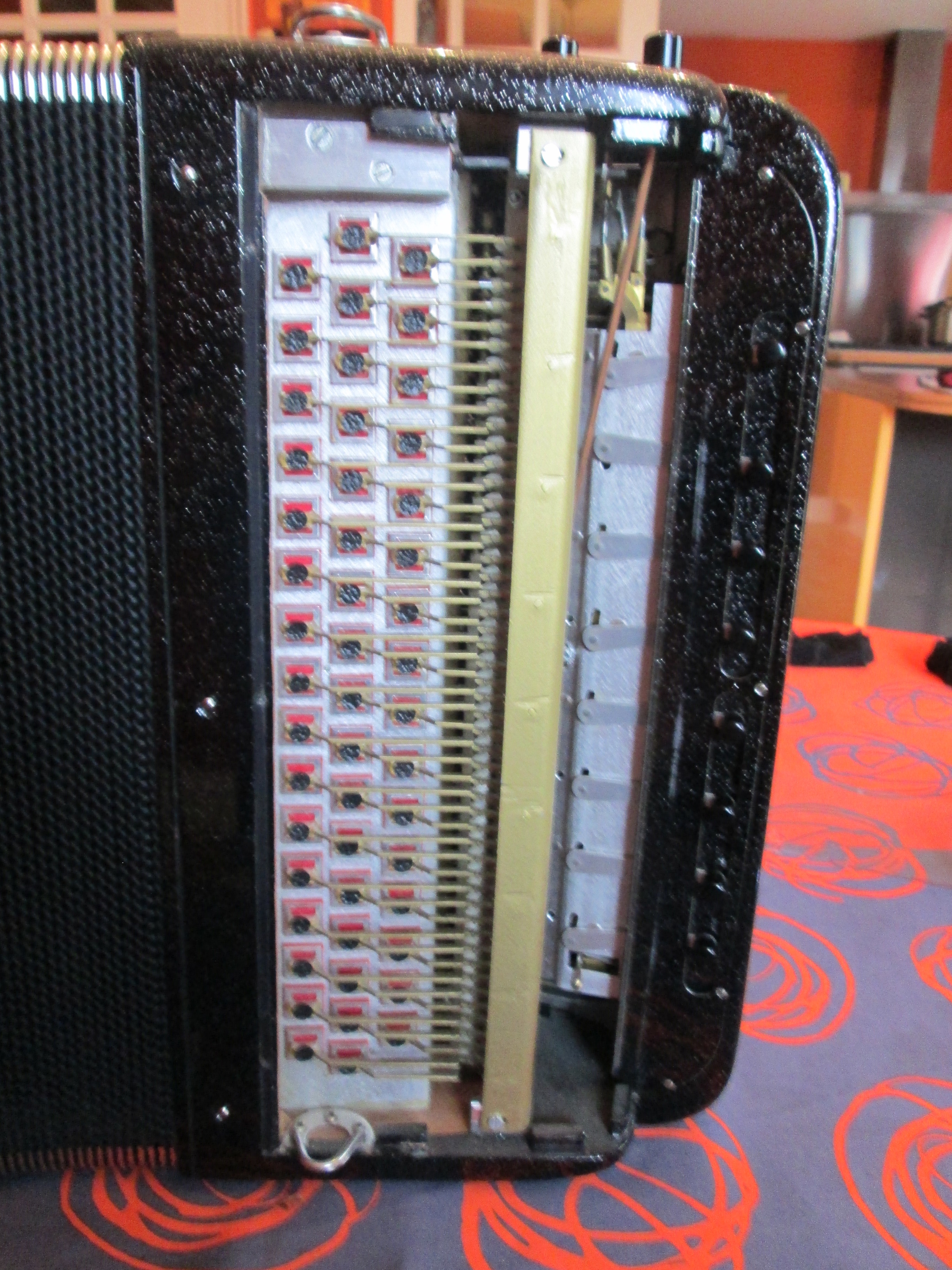
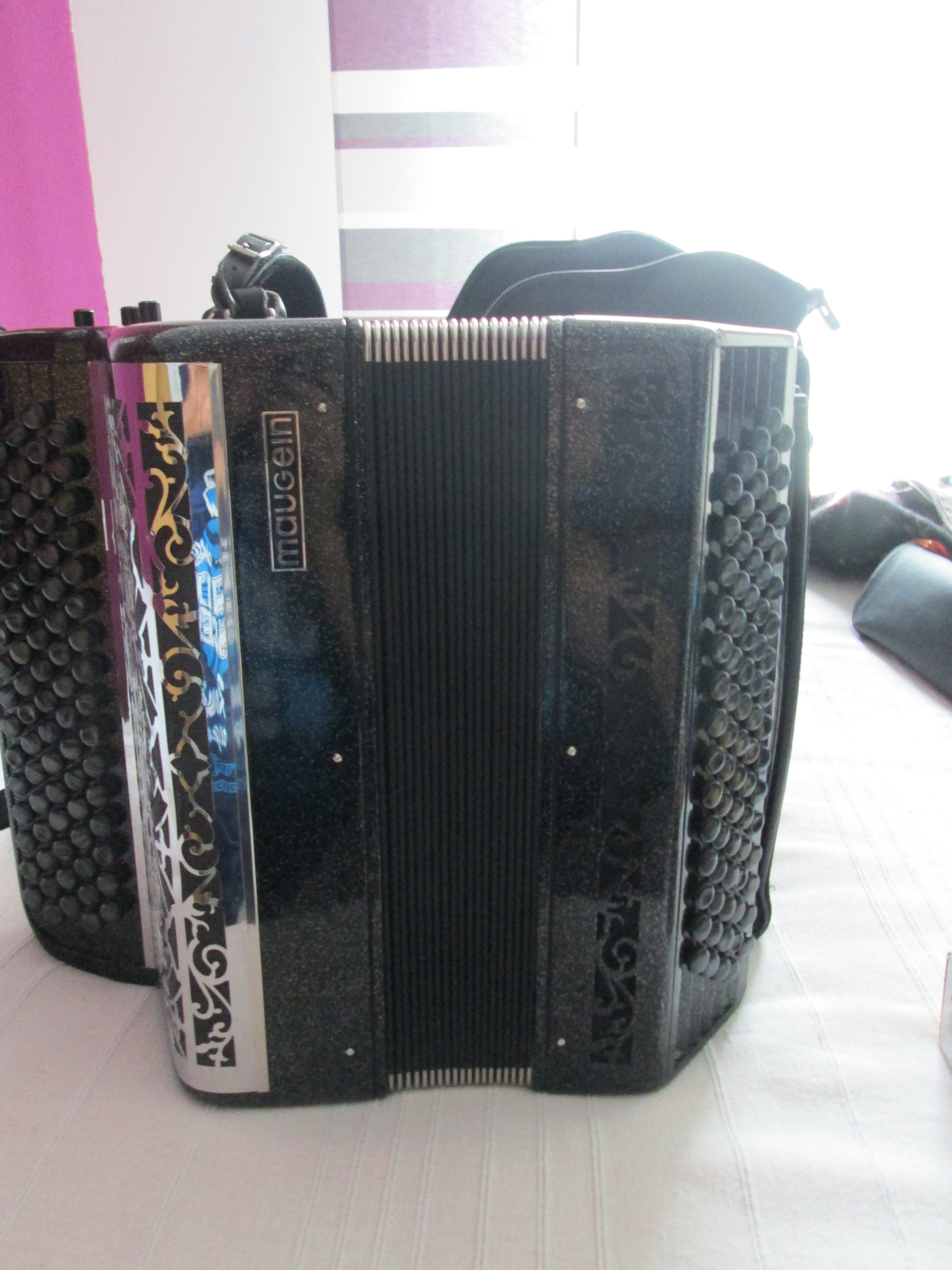
my other accordion with a very old midi interface and contact à ressort just for the look , is a véry old accordion
sorry peter i have some errors ! look the new picture for the matrice .
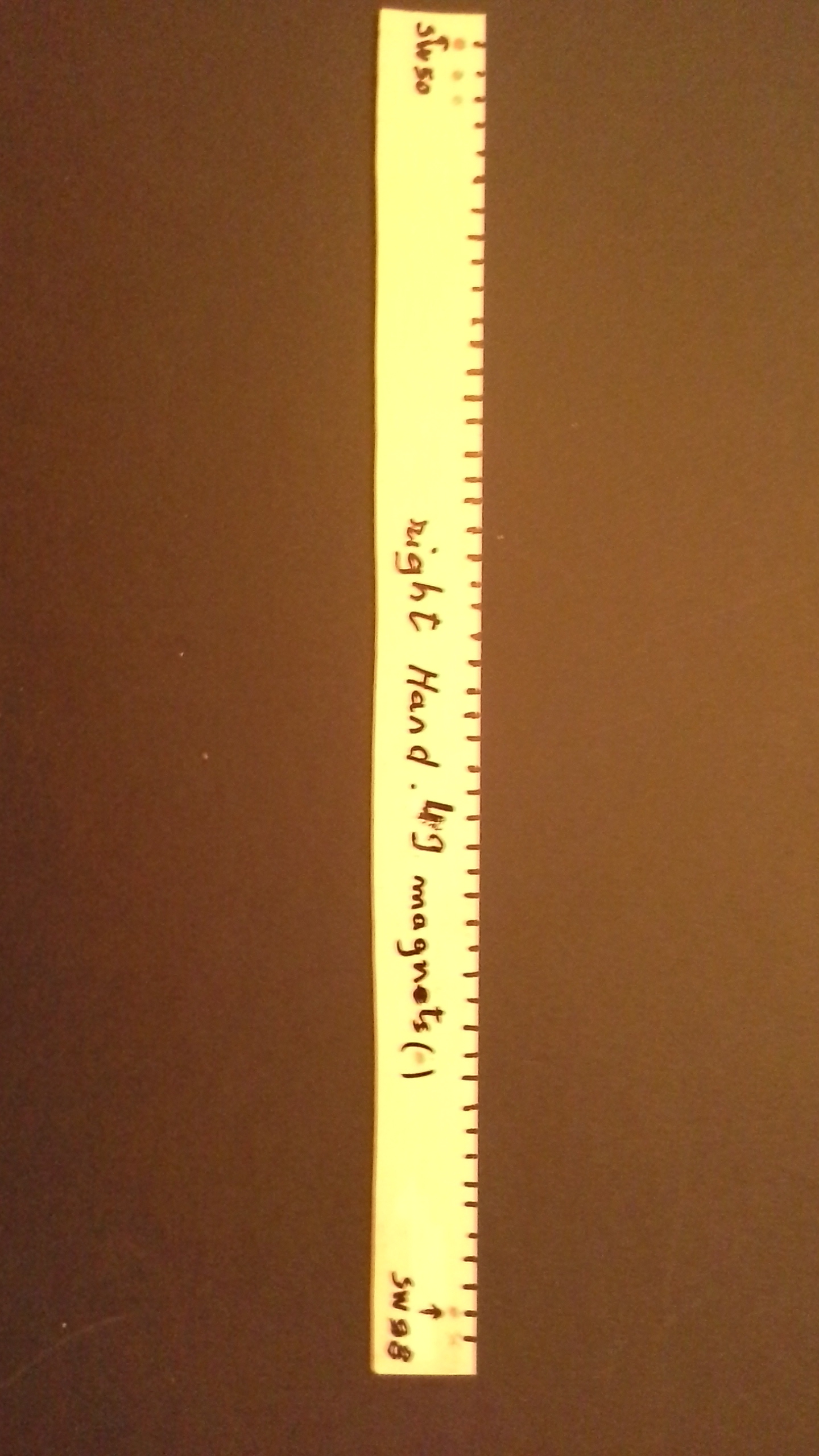
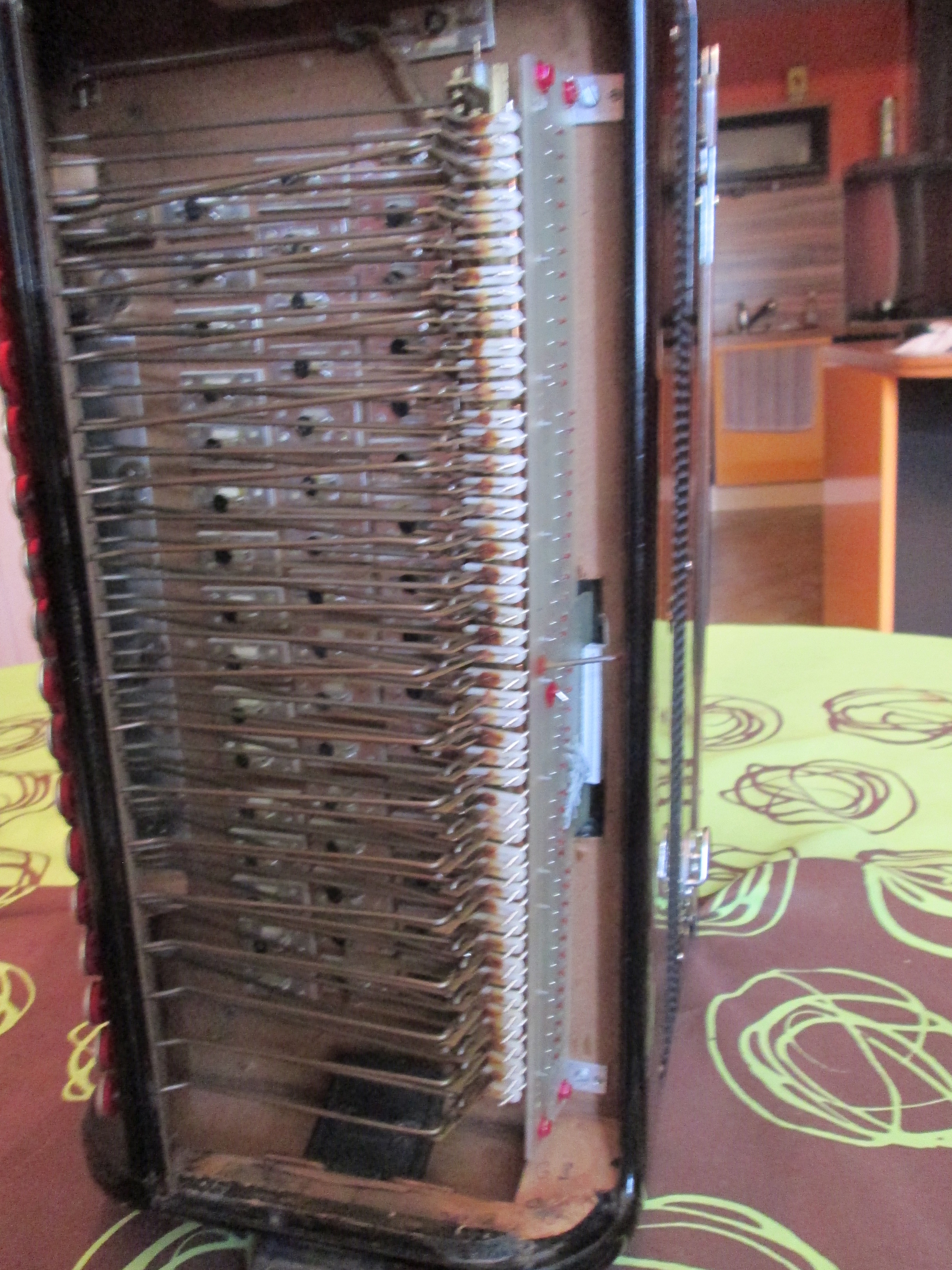
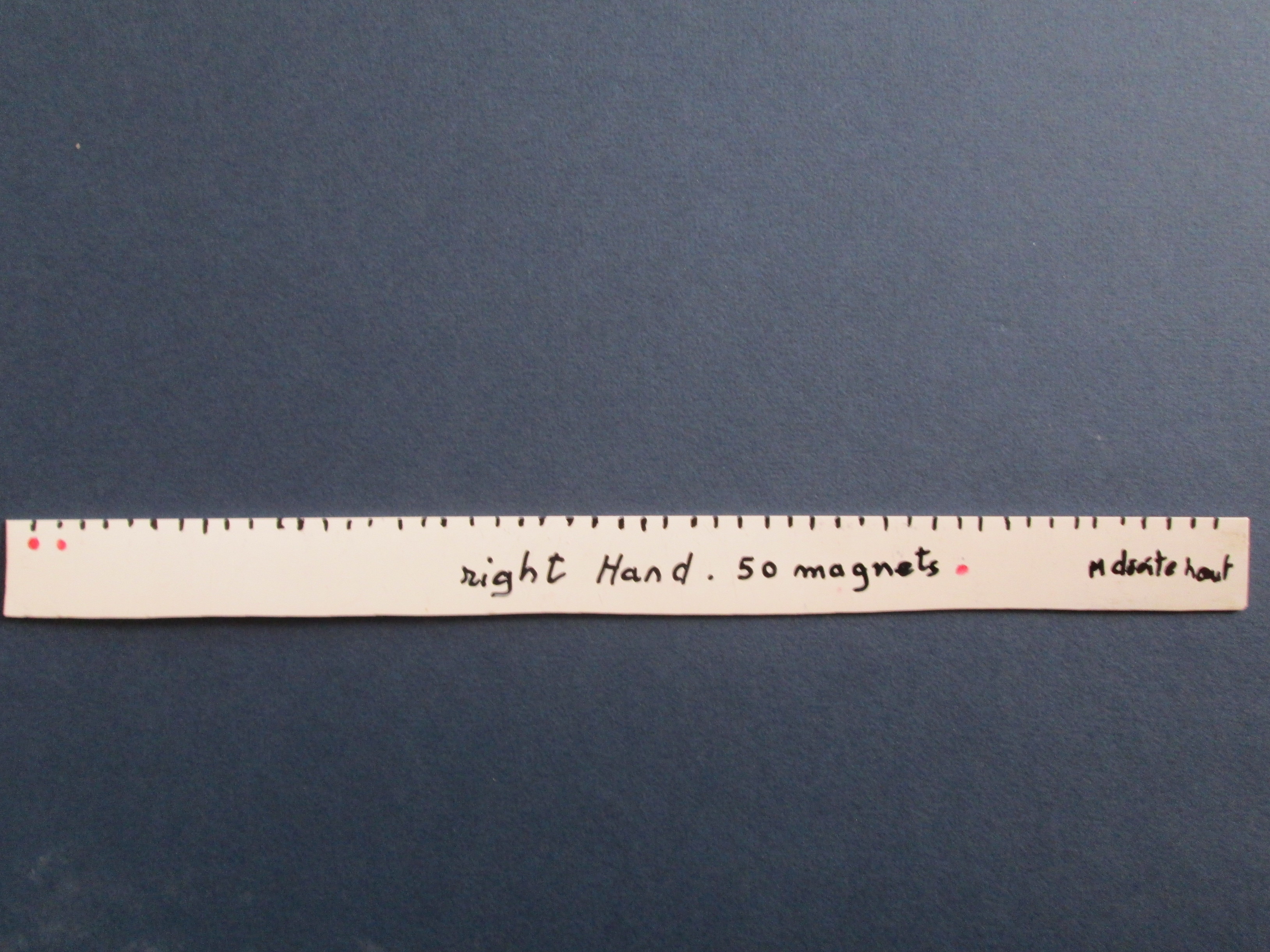
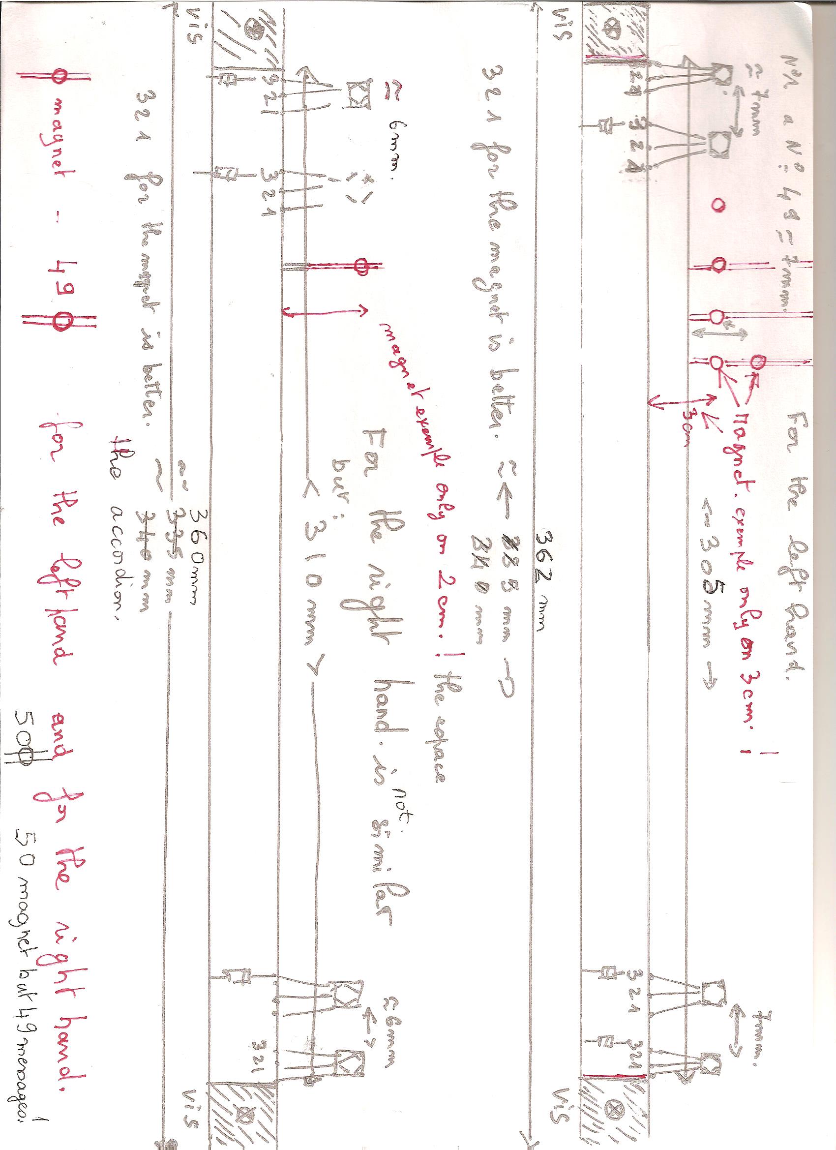
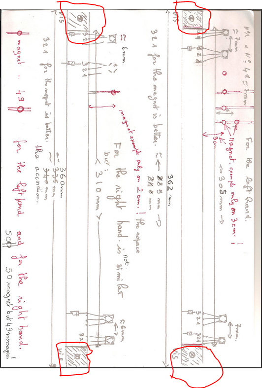
left hand this is exactely 305 mm for the magnets and 362 mm for the total for 49 magnets but for the rignt hand is exactely 310 mm for 50 tiges but my IDE is for 49 magnets! because one touch is not acoustic no sound . I adress the picture for the right hand this is exactely. For theses wires this is very difficult only one cable . I adress other pictures thank you
It is possible with câble only no broches inside soufflet , is so small but somes connectors on the circuit board hall effect sensors
OK, some questions and suggestions:
-
Can both hall effect boards be the same size? If we can make them identical you only need one board instead of two and most board houses give you between 2 and 10 identical boards on a single order. One board saves money and reduces the work a bit.
-
on the board with 50 (instead of 49) sensors, where is the non working (or at least not needed) sensor? It may be easiest to put in all 50 sensors on both boards (if there is room) then just not put a sensor at the non working position. Does that non working position change the pin numbers to the mega at some point or is it just skipped?
-
Do you need mounting holes on the sensor board? If so where and what diameter are the mounting hole or holes.? They are simple to add to the board if I know where they are.
-
When I started at making the wiring in schematic I noticed the sensors are on the pcb backwards (i.e. the pins are 1 2 3 rather than the correct 3 2 1). I assume that is important because the sensor is probably only sensitive on on one side. I am correcting that now and will post in a corrected sketch in a bit.
-
The connectors on the mega: it is possible to get Dupont connectors and a crimping tool on Ebay. That gives you a plastic housing that takes the 6, 8 or 10 wires on the mega and a wire coming out of it for the connection. It is then possible to make a clamp that will hold the connector in place (because you have a longer strip of plastic to work with). That’s probably what I would suggest doing. That may be better than soldering wires as if something breaks you can unplug it rather than having to unsolder wires.
Edit:
Here is a new sketch with 50 sensors in 305 cm. If you print this out at 1 to 1 scale then you can see if 1 board will work for both sets of sensors. If that won’t work it would be useful to know what changes need to be made to make each of the boards work.
accordion-Sketch.fzz (46.9 KB)
Peter
2 -oui les 2 tableaux à effet peuvent avoir la même dimension 360 mm On fait les 2 cartes de la même façon. On installe 49 capteurs pour les 2 planches . le N°50 c’est " sw 99 D99" !!! look : tom scarff
2- distance 7 mm / 6 mm ?
3 -non pas de trou de montage
4 c’est important pin 3 pin 2 pin 1 car le capteur est plus sensible
5 Je connais les connecteurs dupont mais il faut que ça passe par un trou de 15 mm
thank you
It is correct 7 mm or 6 mm ! i think . Pour ma carte arduino il a rajouté des connections rouges à souder
I think I read somewhere that the PCB has to be 36mm wide - too hard to translate all that again to find it -, but if you look at the magnets on the left side they are 30mm away. Accounting for the A3144 only having 16mm legs, I think the PCB has to be maybe 60mm wide so it can shift up and put the Hall over the magnet.
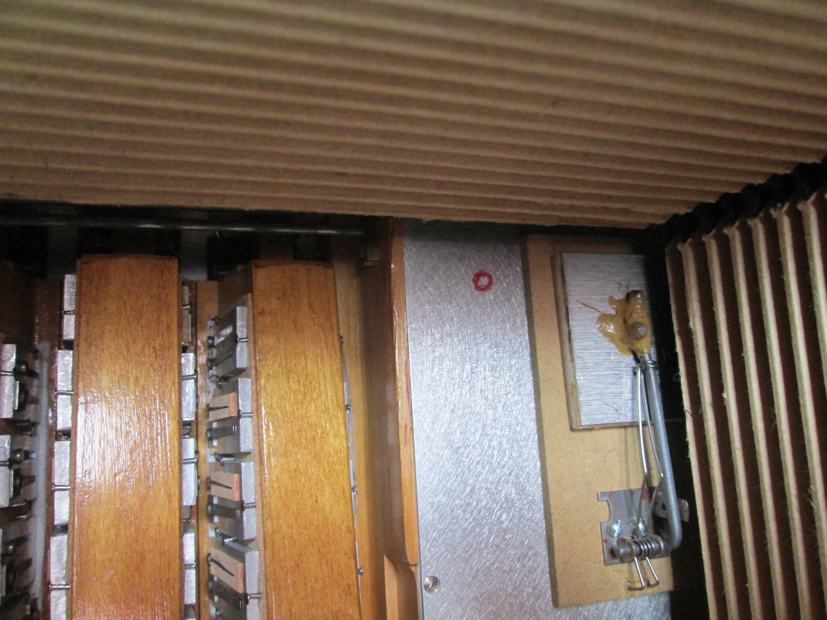
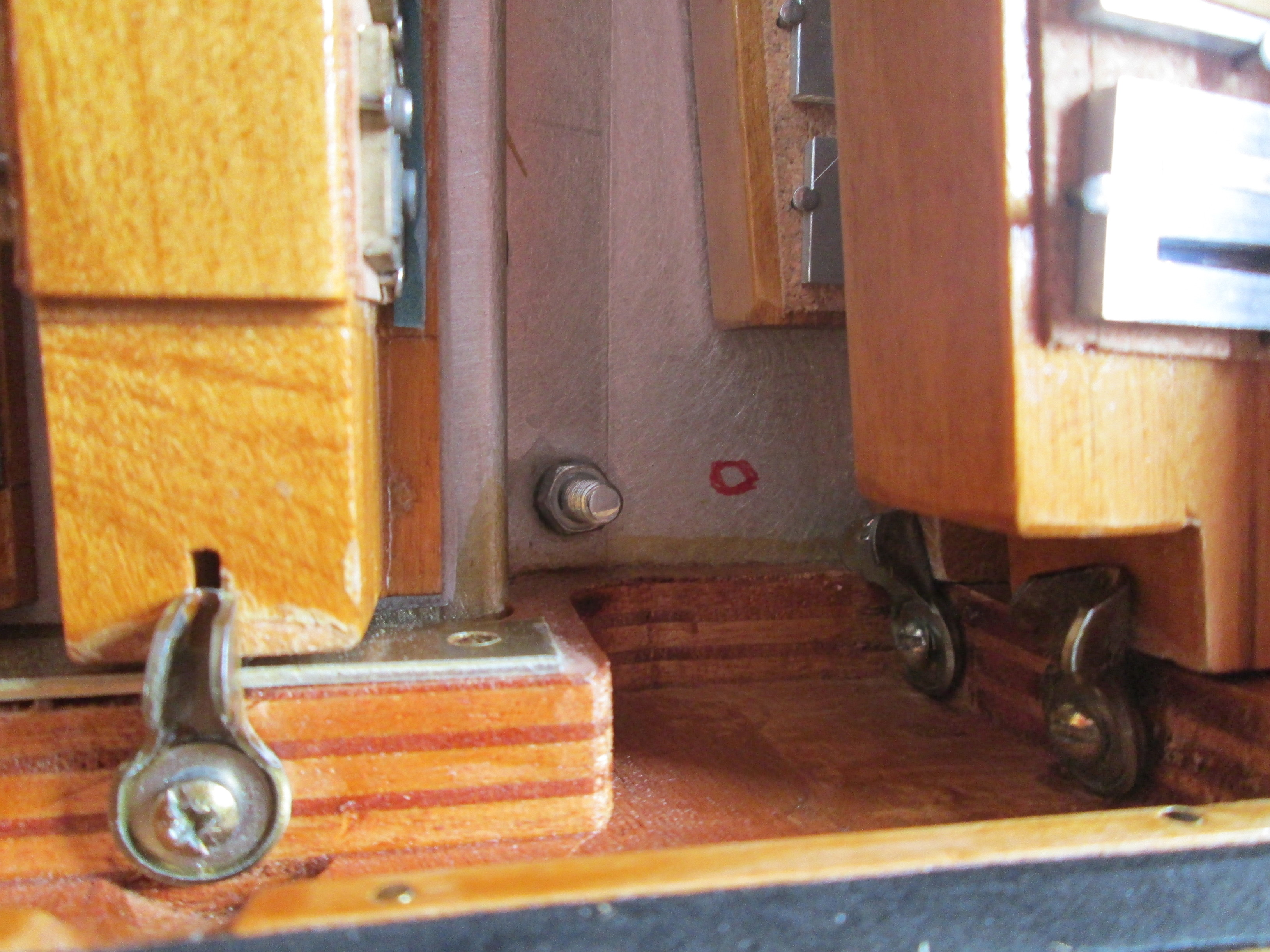
I can’t find a SW99 D99 in tom scarff’s schematic, it seems to end at SW98 as far as I can see, The issue here is where the position with no magnet is because that may affect the wiring to the Arduino. If the no magnet position is not on either end (and it looks to be about 6 sensors from the right in one of the hand drawn images) then the wiring would need to skip that sensor to make the software work because it appears to be only expecting 49 sensors. Could you circle the position with no magnet in this image please? Or probably easier just tell me which sensor number has no magnet. I assume that sensor position would be skipped in the connectiosn to the Arduino mega.
2- distance 7 mm / 6 mm ?
I think I understand, the right hand board (which should be the current sketch) has ~6CM (the actual board has ~6.1 mm spacing) between sensors. So I need to make a second board with ~7mm spacing between sensors (and one more position for the unused sensor) for the left hand side. So we do need two different boards as the spacing is different.
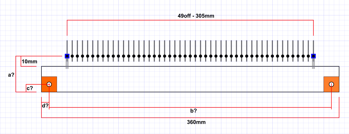
Are you sure you don’t want mounting holes? The current boards seem to have them as shown circled in red in this sketch from above:
it is easy enough to make the holes in the board, I just need the x and y position and the diameter of the hole. You can also drill the hole later as long as we make the board sufficiently wide (the current board is set at 30.5cm, I expect we need to move that up some amount. )
Yes I realized that the sensor was probably more sensitive on one side than the other and reversed the parts on the board so the pins are now the correct 3 2 1 sequence.
That is too bad, the 8pin dupont housing (without pins) is almost exactly 15mm so with pins and wires it wouldn’t fit. You could run the wires through and put the connector on after the wire is through the 15mm hole. If you ever need to remove the wires you would need to remove the pins from the header (which isn’t easy to do) or just cut the wires at the header and crimp a new one on afterwards, but hopefully you won’t ever have to take the cable out and it would allow you to secure the connections to the mega better which would be good.
Peter
Je vous répond précisément demain .les tiges sur lesquelles seront collés les aimants sont de 49 sur la main gauche et sur la main droite 50 tiges mais les schémas ont chacun 49 tiges pour coller 49 aimants et 49 liaisons donc le sw99 n’existe pas donc on ne mets pas de liaison diode effet hall bonne nuit merci philippe