il faut que l’on m’aide pour limiter le nombre de fils en utilisant les composants qui vont matricer les informations ou alors faire en sorte que mes pistes ne se coupent pas . Je ne sais pas faire le dessin et le schéma dans fritzing pour renvoyer chaque pin 1 sur le 5 volt, chaque pin 2 sur le gnd , et chaque pin 3 sur le signal . J’ai trop de fils sur le circuit imprimé que j’ai fait . Sur mon schéma les pistes se croisent comment on fait dans fritzing merci pour votre réponse
I need help to limit the number of threads using the components that will write the information or so that my tracks do not intersect. I do not know how to do drawing and drawing in fritzing to return each pin 1 on the 5 volt, each pin 2 on the gnd, and each pin 3 on the signal. I have too many wires on the circuit board that I made. On my schematic the tracks intersect how we do in fritzing thanks for your answer
That we should be able to do fairly easily. If you post the sketch (the .fzz file) of your Fritzing sketch the same way you posted the pictures we can fix up the sketch and post it again so you can download it and try it. I expect the important part is going to be to figure out the spacing of the hall effect sensors in pcb, the rest looks fairly easy.
Peter
Que nous devrions pouvoir faire assez facilement. Si vous postez l’esquisse (le fichier .fzz) de votre esquisse Fritzing de la même manière que vous avez posté les images, nous pouvons la corriger et la poster à nouveau afin que vous puissiez la télécharger et l’essayer. Je m’attends à ce que l’important soit de déterminer l’espacement des capteurs à effet Hall dans le circuit imprimé, le reste semble assez facile.
merci pour votre réponse . Mais je ne sais pas faire d’esquisse . Ce n’est pas moi qui est fait le schéma de principe . Les capteurs ne seront pas tous droit , il peuvent être soudés un peu en biais car il y a des décalages ou alors il faut réduire un peu le percage à - de 2.54 .rampe capteur accordéonUntitled Sketch.fzz (46.5 KB)
ce n’est pas complet et je ne sais pas faire j’ai juste installé l’application fritzing il y a 2 jours !!!
I kind-of felt that he wanted help making a sketch in FZ.
If you want to use BB view as the master for connections - most people use SCH view -, you must make the BB view correct.
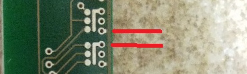
Wires touching in BB view are not connected. If you click on green pin F8 on the first BB the pin holes turn yellow. Now look at pin F4, it is not yellow. These 2 wires are not connected.
Si vous souhaitez utiliser la vue BB en tant que maître pour les connexions (la plupart des gens utilisent la vue SCH), vous devez corriger la vue BB.
Les fils se touchant dans la vue BB ne sont pas connectés. Si vous cliquez sur la broche verte F8 sur le premier BB, les trous pour les broches deviennent jaunes. Regardez maintenant la broche F4, elle n’est pas jaune. Ces 2 fils ne sont pas connectés.
There are youtube tutorials, maybe some are subtitled in French.
Il existe des tutoriels youtube, certains sont peut-être sous-titrés en français.
EDIT - I just found out there is no Hall sensor in FZ, but then again he might need one with 2mm spacing.
Now we need to know the desired distance between the two red lines (i.e. the spacing between the hall effect sensors on the pcb) in inches or mm and we should be able to do this.
It’s a bit hard to follow what’s going on because the translation isn’t great, but I think we need the spacing of the magnets. Then again there is a thing with switches.
I read 305mm, then something 335mm, it all gets confusing. We really need a mech drawing.
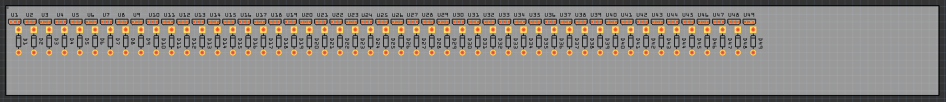
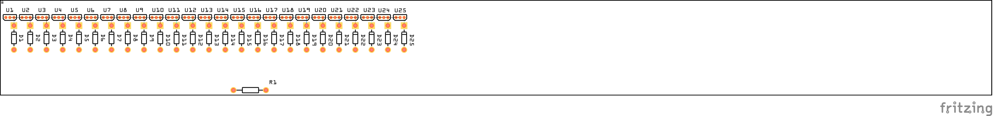
305m is the max size of the board, it is going in to a space that is 335mm long as I read it. The extra space has something else in it I assume. I’m redoing the small signal diodes I did a couple of years ago because they are needed here, then I’ll try a minimum space board with 49 hall effect sensors and see how long that is.
OK, I did about 25 (a bit more than half) of the sensors on a 30cm by 3CM PCB. With half done we are using less than half the board space so fitting 49 sensors in to 30Cm shouldn’t be a problem. It is currently late here so I’ll continue this tomorrow. If you can supply the desired spacing between sensors it is easy to move the sensors in to the position you want them (and the leads will allow you to adjust them one way or the other for a short distance as well.)
You can box copy blocks of parts - you have to start the box in a blank area and not on the BB -, hold CTRL and click on the BB to deselect it, and then just copy paste and move that block of parts. If you want the parts in the other views to move in an orderly pattern you have to line the parts in a row before hand, which you have done, and it will copy the parts in a row in the other views when you copy the BB parts.
I don’t know if the Hall SCH is the best for packing 49 parts in a row, maybe something more compact.
I personally wouldn’t even do a BB view, only a SCH and PCB, because it just seams like more work for something that will not be made in real life.
Wish I’d read that before finishing this , I tried selecting a bunch and copying but was on bb and didn’t use cntrl and it didn’t work so I did it manually.
as you see we have room at the end if needed. So to go forward I need to know what spacing between the sensors you would like and how the 8 connections to the mega are made. The choices would look to be a 8 pin header (which provides either holes for wires or a header to plug a cable in to, or an 8 pin dual row header to take an 8 conductor IDC ribbon connector cable. Which would you prefer? Also where do you want the connector, left end, right end, middle of the board or somewhere else. All the parts need to be placed before routing the pcb. Does anything else (such as the switches in the schematic) need to go on this board as well or is it only the hall sensors and the diodes.?
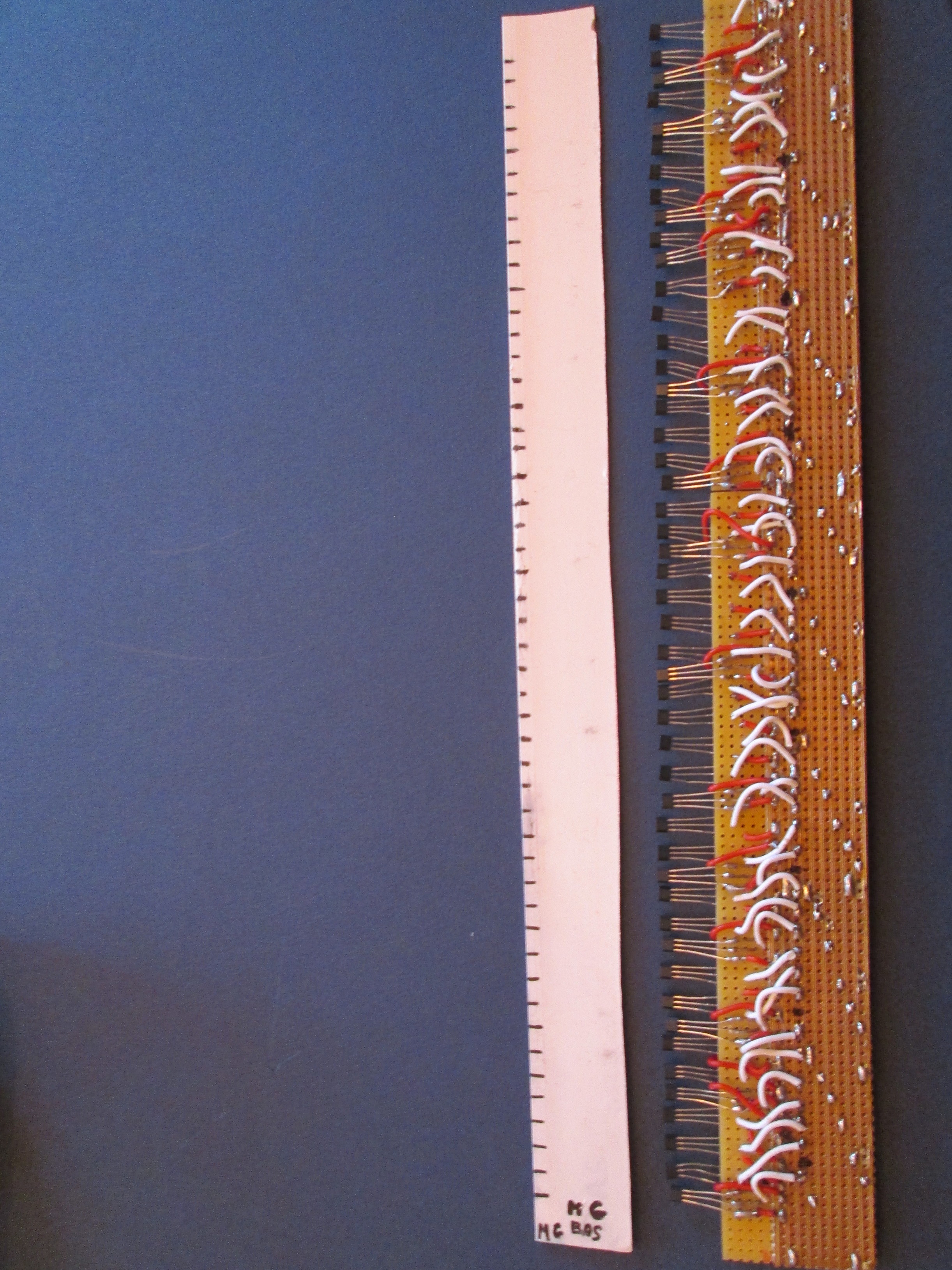
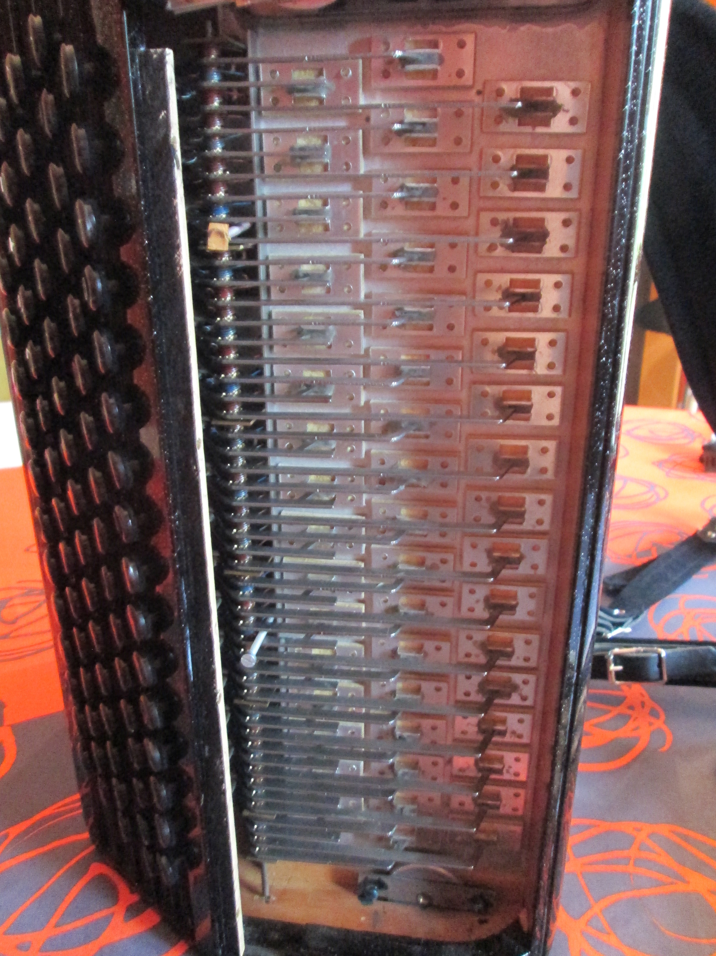
Bonjour peter , je vous joint une photo; Sur cette photo il y a la photo de mon circuit left hand du capteur de 1 à 49 sur 300 mm exactly with the hall effect sensor just in face of the black trait on the white réglette this is my matrice because every 49 magnet are stick on la soupape do do # ré # mi …look the second photo . For les wires , look the schéma tom scarff vers la arduino mega 23 25 27 29 31 33 35 37 39 22 … with X2 : 32 30 26 24 22 pontés entre eux and for push button 4 . I think qu 'il faudrait un connecteur au centre de la carte qui reprenne le maximum de wires en nappe sauf les interrupteurs et la broche midi . thank you peter
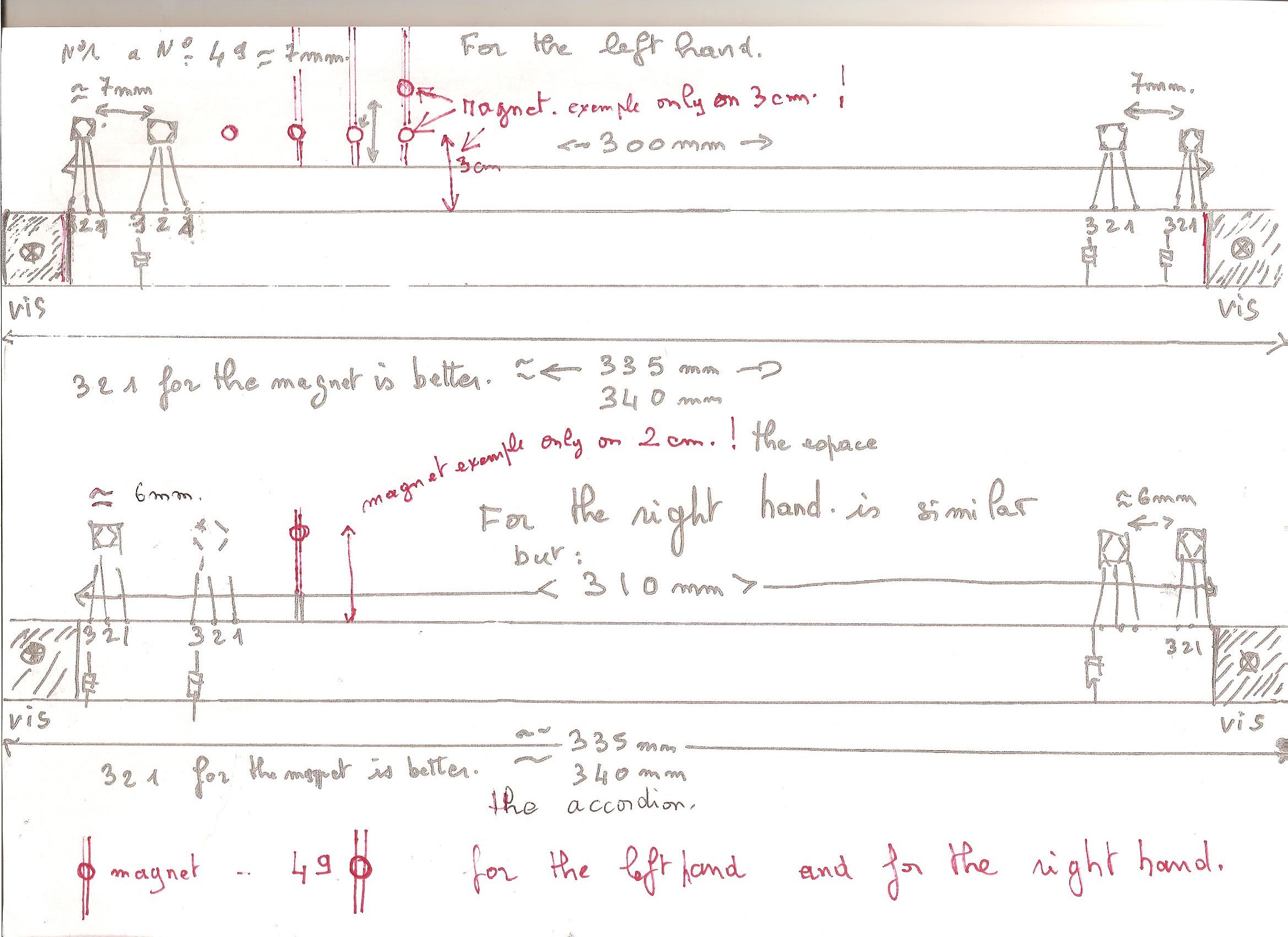
Bonsoir, c’est très difficile de vous donner une mesure exacte la seule mesure exact elle est entre la
1 ière tige et la 49 ième tige . Je vous envoie un petit croquis merci pour votre aide philippe
Je pense qu’en prenant la pin 2 du capteur à effet hall comme repère avec mon croquis on à pour la main droite 6 mm et pour la main gauche 7 mm entre les capteurs . Mais supports pour les magnets , les tiges ne sont pas exactely à la même distance .
 , I tried selecting a bunch and copying but was on bb and didn’t use cntrl and it didn’t work so I did it manually.