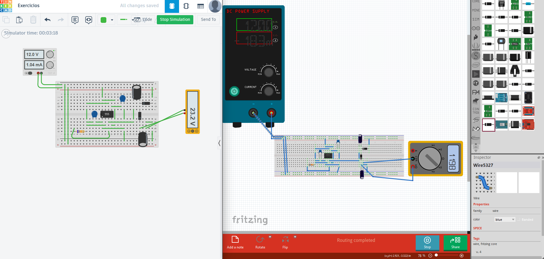
Hi, I would be glad if anyone could help me confirm whether I’m wrong or not. As you can see in the image below, I have a simple circuit using the IC555. It works in TinkerCad but not in Fritzing. I tried all the available diodes, but the result was the same. Has anyone experienced a similar issue when using different simulators?
555.fzz (9.5 KB)
For me it gives a spice error, although the diodes appear to have the same spice model as the one in the simulation bin, but that may not be the part it is unhappy with.
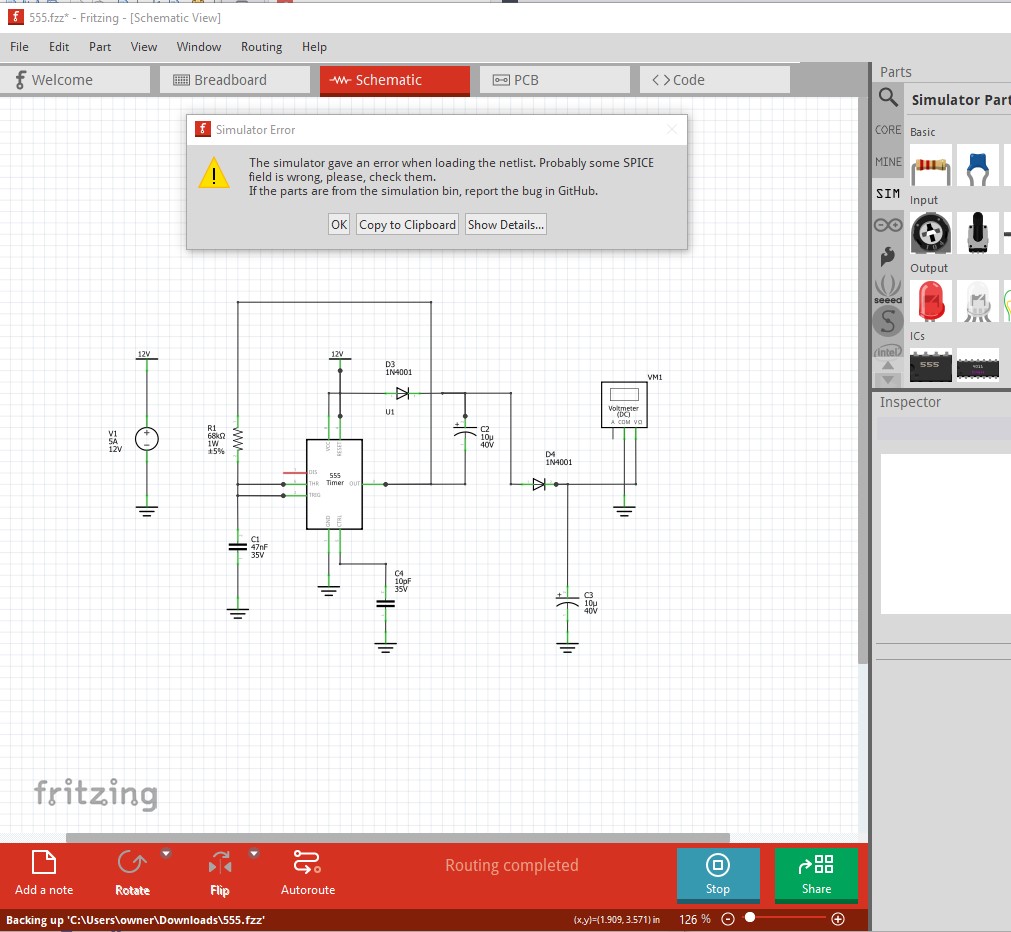
The simulator gave an error when loading the netlist. Probably some SPICE field is wrong, please, check them.
If the parts are from the simulation bin, report the bug in GitHub.
Errors:
stdout Note: No compatibility mode selected!
stdout Circuit: simulator netlist
stderr Warning: Model issue on line 4 :
stderr .model labpowersuppymodel ilimit(r_out_source=1 r_out_sink=1 i_limit_sou …
stderr Unknown model type ilimit - ignored
stderr Error on line 7 or its substitute:
stderr av1 4_v1_aux 4_v1_aux2 0 4 labpowersuppymodel
stderr MIF-ERROR - unable to find definition of model labpowersuppymodel
Netlist:
Simulator Netlist
D3 4 3 DI_1N4001
XU1 6 1 4 5 6 7 4 0 UA555
.model labPowerSuppyModel ilimit(r_out_source=1 r_out_sink=1 i_limit_source=5 i_limit_sink=5)
V1Aux 4_V1_aux2 4_V1_aux 5
V1 4_V1_aux 0 12
AV1 4_V1_aux 4_V1_aux2 0 4 labPowerSuppyModel
C1 6 0 47n IC=0
C3 0 2 10u IC=0
- Multimeter, com probe connected to 0 and voltage probe connected to 2
D4 3 2 DI_1N4001
C4 5 0 10p IC=0
C2 1 3 10u IC=0
R1 1 6 68k
*SRC=1N4001;DI_1N4001;Diodes;Si; 50.0V 1.00A 3.00us Diodes, Inc. diode
.MODEL DI_1N4001 D ( IS=76.9p RS=42.0m BV=50.0 IBV=5.00u CJO=39.8p M=0.333 N=1.45 TT=4.32u )
.SUBCKT UA555 32 30 19 23 33 1 21 999
* TR O R F TH D V GND
*
* Taken from ngspice examples: ngspice/examples/p-to-n-examples/555-timer-2.cir at master · imr/ngspice · GitHub and modified to include the ground. And this model has been…
* Taken from the Fairchild data book (1982) page 9-3
*SYM=UA555
*DWG=C:\SPICE\555\UA555.DWG
Q4 25 2 3 QP
Q5 999 6 3 QP
Q6 6 6 8 QP
R1 9 21 4.7K
R2 3 21 830
R3 8 21 4.7K
Q7 2 33 5 QN
Q8 2 5 17 QN
Q9 6 4 17 QN
Q10 6 23 4 QN
Q11 12 20 10 QP
R4 10 21 1K
Q12 22 11 12 QP
Q13 14 13 12 QP
Q14 999 32 11 QP
Q15 14 18 13 QP
R5 14 999 100K
R6 22 999 100K
R7 17 999 10K
Q16 1 15 999 QN
Q17 15 19 31 QP
R8 18 23 5K
R9 18 999 5K
R10 21 23 5K
Q18 27 20 21 QP
Q19 20 20 21 QP
R11 20 31 5K
D1 31 24 DA
Q20 24 25 999 QN
Q21 25 22 999 QN
Q22 27 24 999 QN
R12 25 27 4.7K
R13 21 29 6.8K
Q23 21 29 28 QN
Q24 29 27 16 QN
Q25 30 26 999 QN
Q26 21 28 30 QN
D2 30 29 DA
R14 16 15 100
R15 16 26 220
R16 16 999 4.7K
R17 28 30 3.9K
Q3 2 2 9 QP
.MODEL DA D (RS=40 IS=1.0E-14 CJO=1PF)
.MODEL QP PNP (BF=20 BR=0.02 RC=4 RB=25 IS=1.0E-14 VA=50 NE=2 CJE=12.4P VJE=1.1 MJE=.5 CJC=4.02P VJC=.3 MJC=.3 TF=229P TR=159N)
.MODEL QN NPN (IS=5.07F NF=1 BF=100 VAF=161 IKF=30M ISE=3.9P NE=2 BR=4 NR=1 VAR=16 IKR=45M RE=1.03 RB=4.12 RC=.412 XTB=1.5 CJE=12.4P VJE=1.1 MJE=.5 CJC=4.02P VJC=.3 MJC=.3 TF=229P TR=959P)
.ENDS
.option savecurrents
.option interp
.OP
*.TRAN 1ms 100ms
- .AC DEC 100 100 1MEG
.END
Note I know almost nothing about simulation @fai (who wrote the simulation code) will probably be able to give you a better answer.
Peter
1 Like
Thanks for replying. Although I’m not using parts from the simulator bin (all the parts I used are from the core section), I’m analyzing the information you sent and will check if the same issue occurs on my end so I can report it as a bug.
I see that power supply isn’t in the simulator bin. That may mean that while it has a spice model (which my original did not), that it doesn’t work yet and thus isn’t yet capable of simulation. You might try replacing it with one of the batteries in the simulation bin. It appears (although I am far from sure!) to be objecting to something in the power supply spice model so this may be normal behavior. The simulator is a work in progress.
Peter
Hi @leandroding @vanepp I’ll reproduce the sketch to see what’s wrong
1 Like
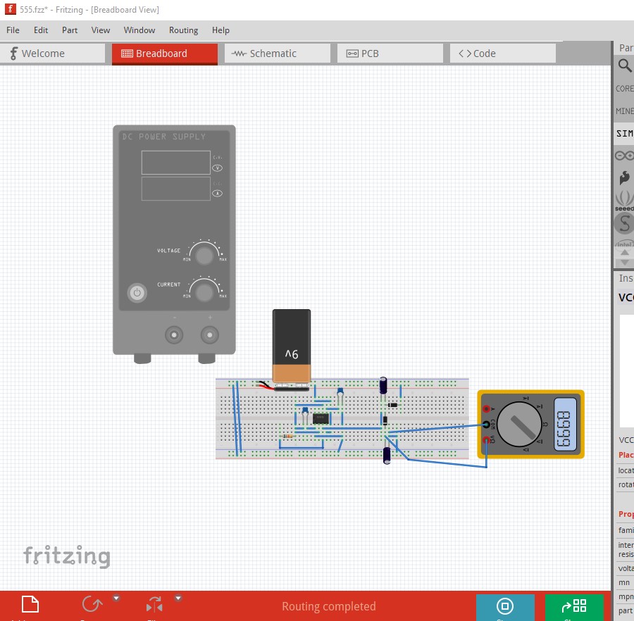
OK very strange
For me turns up no warning – simulation runs; nothing in multimeter
I’ll recreate it from scatch
I think I found the problem @leandroding @vanepp
But that did not change anything. It might be the simulation code in the app
Edit:
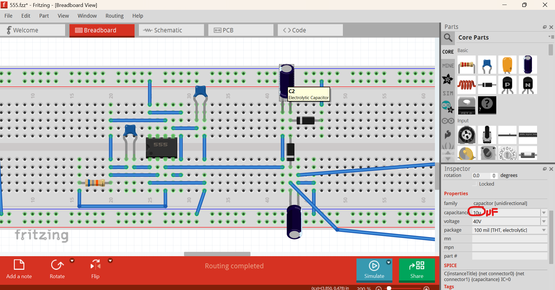
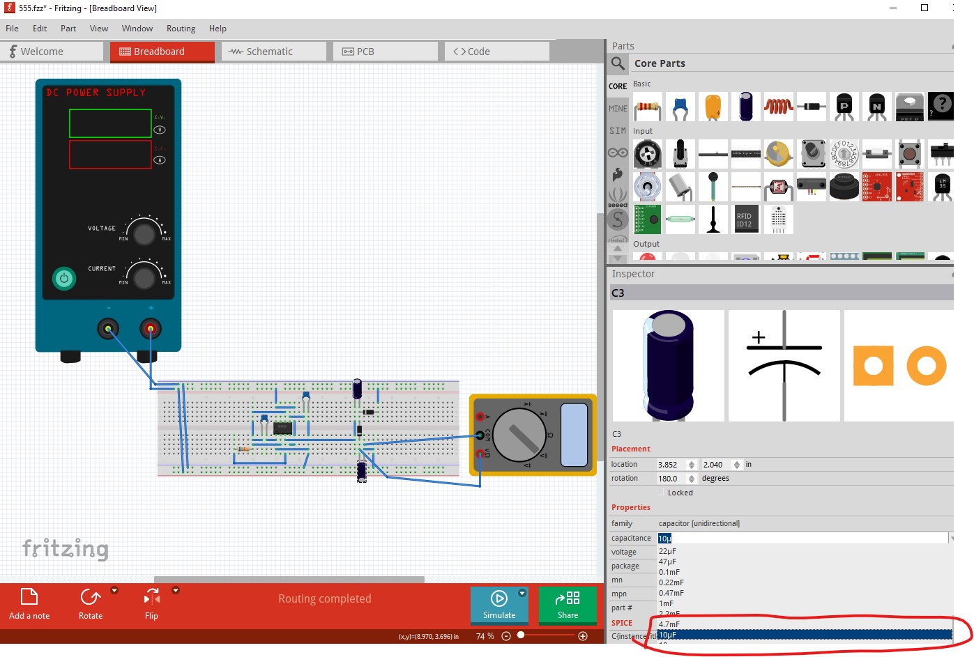
It will not be possible to key in 10µF. @leandroding How did you do so?
Likely via the pull down menu which will set it.
I expect the issue is a bad spice entry in the power supply although it is odd that it isn’t flagging the error for you. That is likely why the power supply isn’t in the simulate bin because it doesn’t work correctly yet.
Peter
Even then not working. I trialled and error, tried transient mode, but still no
Try replacing the power supply with a battery from the simulation bin. I expect that will work.
Peter
1 Like
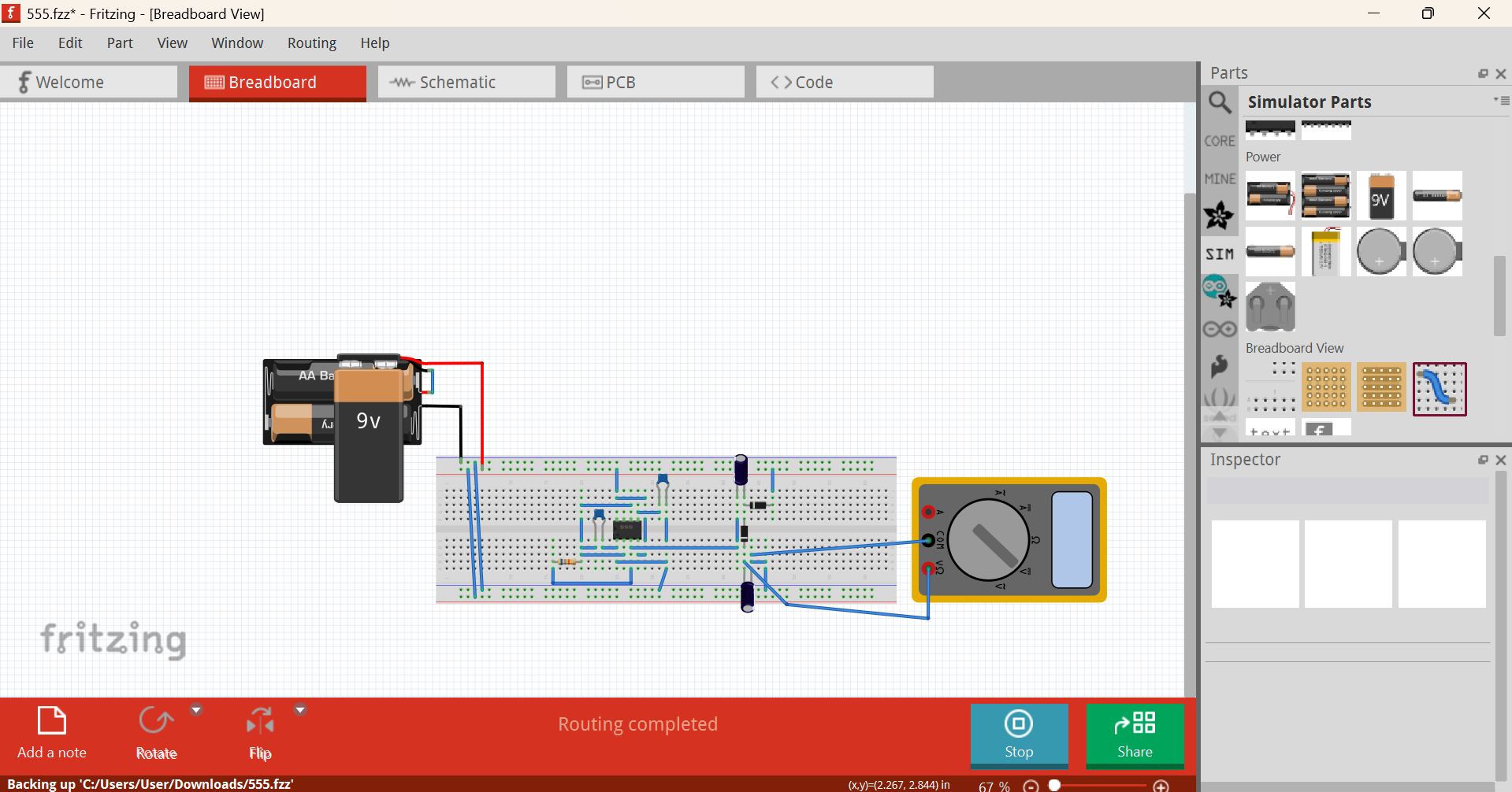
Huh! Does for me.
I have no idea if it is right or not as I don’t know what the result expected it, but it simulates without complaint and outputs a voltage on the meter.
Peter
1 Like
Just insert using Alt+0181 or by typing ‘u’
I believe that using a battery has the same effect as using a DC power supply. The purpose of the circuit is to double the input voltage (Vin), with a maximum output capacity of 24V. So, if a 9V battery is used, the output should be approximately double that. Since the circuit works correctly in another simulator, I will go ahead and report this as a bug on GitHub myself. Thank you all very much for helping me confirm this information.
Be aware that the simulator currently only does static simulation (not dynamic unless you enter debug mode and enable it, as it is not complete yet AFAIK.) So you will only get the static dc state which likely won’t include voltage doubling (since that would require dynamic state.) As I said I know relatively little about simulation so this may not be correct, but I think this is likely a current implementation limitation rather than a bug. It may work if you enable the dynamic simulation code under debug (which does do dynamic simulation as far as I know.) I think there is a forum post (a search for simulator or simulation should find it) that explains how to enable dynamic simulation. No harm in opening an issue on github, but I expect you may get a similar answer from someone who knows what they are talking about.
Peter
1 Like
Ah, understand know. I am searching for how to enable dynamic simulation and learning about it so I can see if it works or not. Thanks for that information!
These two posts may give some help. The first points to the simulator documentation from the author and mine sort of describes in not much detail how to get in to debug mode.
Peter
1 Like
Hi,
The power supply is working in 1.0.5 (official version). It needs an extra file that the simulator needs to find (abalog.cm, available in ngspice distributions). Unofficial binaries (e.g. from Linux repositories) may not have this packed correctly (it is a very beta feature).
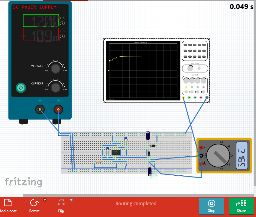
This circuit needs a transitory simulation, and to setup the time of the simulation properly (using the right time step). To do that, run fritzing with the -d option from the terminal. That will enable the transitory simulation. Then, add an oscilloscope to select the sim time and time step (check preferences menu). And then activate the transitory simulation in the arrow of the sim button.
If you do that, you will see the right results (I hope, I did not check the circuit but I get around the double of the voltage). See below
Andres
2 Likes
On the official 1.0.5 release from Fritzing.org on Win10 I get the listed error message although apparently @RAPTOR7762 does not. I suppose I could try reloading 1.0.5 to see if that clears it though.
Peter
1 Like
I also git mine from the official release.
Edit:
In case anyone wondering how to do run fritzing via command line here’s what I did
Microsoft Windows [Version 10.0.26100.4652]
(c) Microsoft Corporation. All rights reserved.

C:\Users\User>cd C:\fritzing.1.0.5

C:\fritzing.1.0.5>Fritzing1.0.5  # This starts Fritzing normally

C:\fritzing.1.0.5>Fritzing1.0.5 -d  # This starts Fritzing in Debug mode

C:\fritzing.1.0.5>
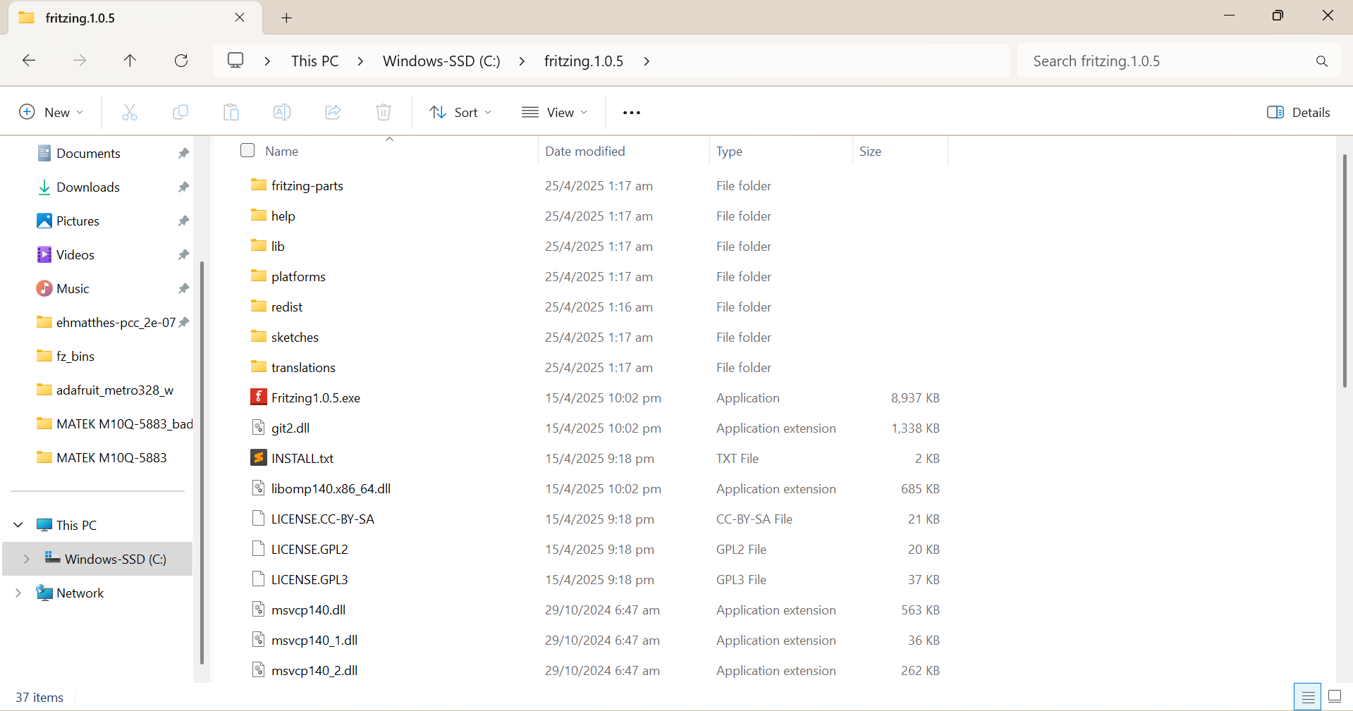
Your’s may be a little different as my file structure is like this
@leandroding Hope mine and Failiz’ message helped!
1 Like