Windows 10, 15 Gigs of RAM, Fritzing 0.9.3
You say you have 0.9.4b, but a Fritzing “Check for updates” says there’s no newer version than my 0.9.3 ?
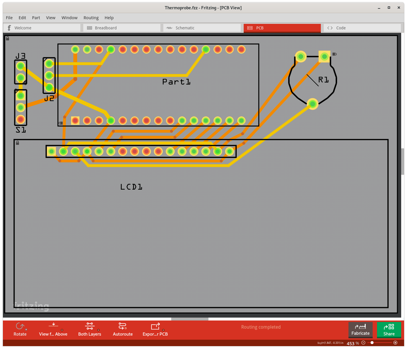
EDIT: >>> I looked directly on the Fritzing site, and found a link to 0.9.4.64. I installed it, and both the Export to Gerber and Design Rules Check now work. My only problem now is the ‘extra’ traces Fritzing has added to the schematic and PCB.
[quote]
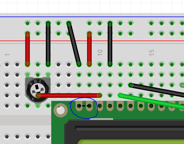
I see something suspicious. both ends of the potentiometer are connected to 5V. I think that is supposed to be used as a voltage divider, to provide a reference voltage to control the brightness of the display. In that mode, one end should go to 5V, the other to ground.[/quote]
Good catch… Its right on the ‘real’ breadboard, but I’d done it wrong on the ‘virtual’ one. I’ve corrected it.
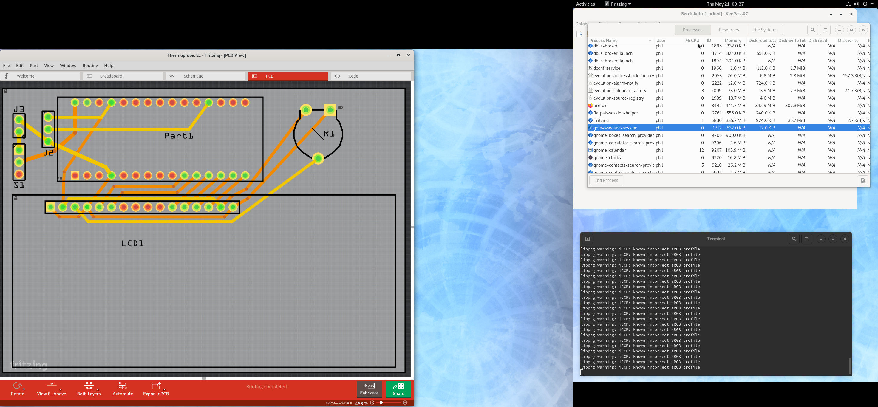
Hmmm, that brings up another bug. When I try to run the design rules check, the progress bar gets to 2%, and Fritzing crashes and closes.
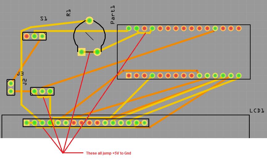
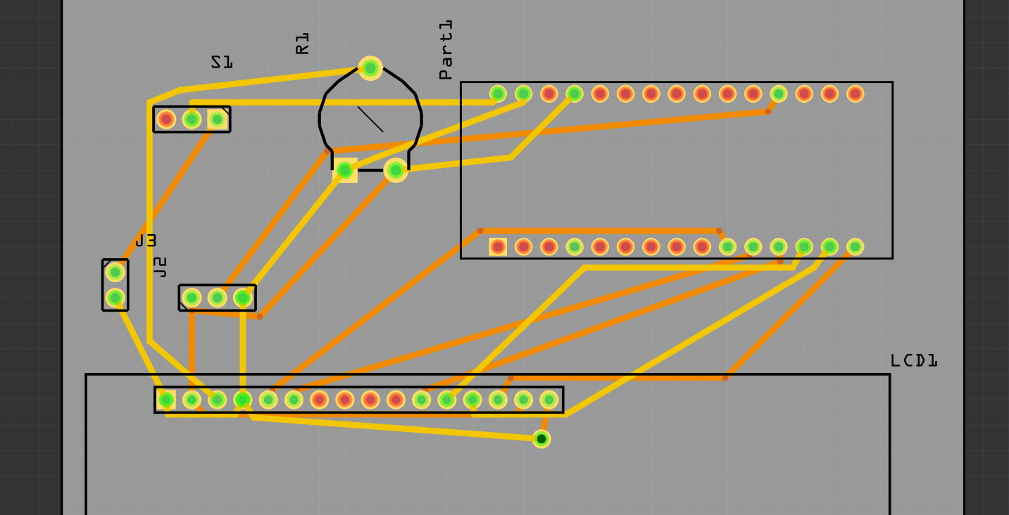
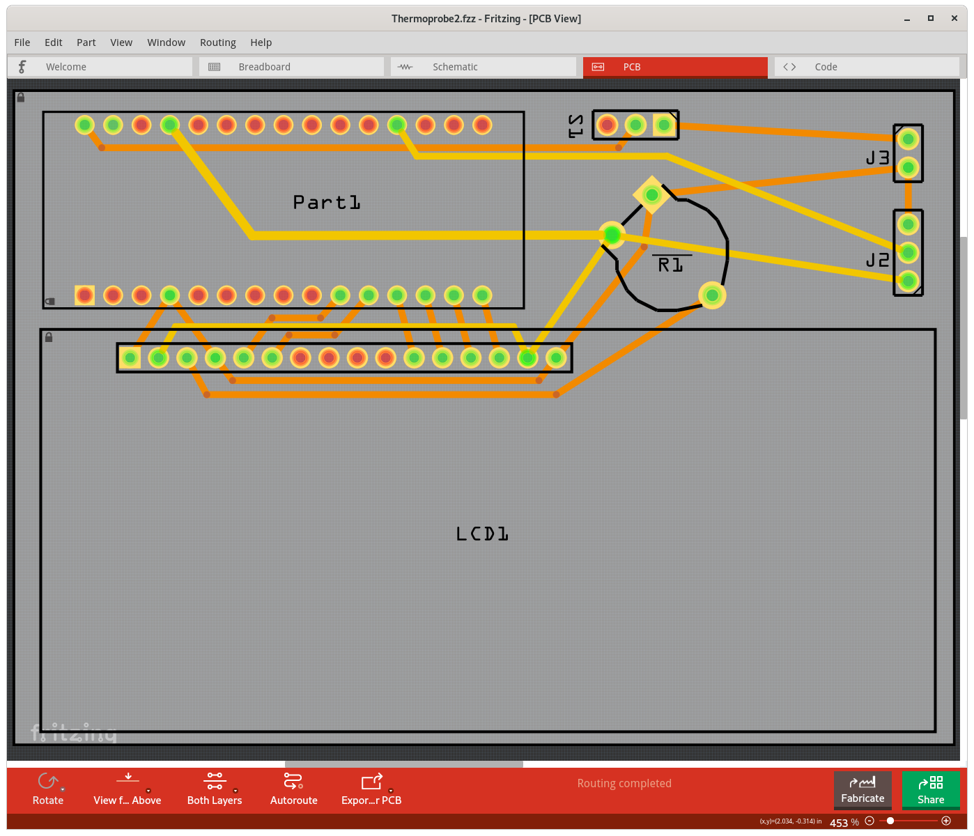
I’ve been studying the traces, and I see a bunch of traces on the PCB, and wires on the schematic, that don’t correspond to actual wires on the breadboard.
For example, Fritzing added a wire connecting LCD 15 & 16 - the +5V & Gnd for the LED, and one connecting the Arduino +5V & Gnd. Another connects J3 pins 1 & 3, which ar +5V & Gnd for the sensor.
If I delete them, and run autoroute again, it puts them back,
Thanks for your help
Thermoprobe.fzz (14.0 KB)