I am sure this is a simple process but can’t find out how to load my custom board into Fritzing so I can use it as the pcb board. I have created the board in Inkscape with the two layers and saved it as an SVG file. But can’t figure out how or where to put it in Fritzing. All I can find is about parts editing not the basic board. Thanks for the help.
In fritzing search for the word custom. It should give you a round white disk called custom PCB image. Drag that out and then in the inspector load image file.
Before you do that be sure to set the page size in Inkscape to be the same as your PCB. File/Document Properties/Resize page to content. (be sure to have all of your svgs selected before resizing)
Thank you very much. I knew it would be easy once you know how. lol.
Don’t be surprised if your PCB shape appears broken. Fritzing wants things a very specific way and it’s really easy to do something in Inkscape that Fritzing will not like. You can check this thread Inkscape Tips and Tricks for solutions to common Inkscape issues.
I must have beginners luck as it worked first time and even OshPark liked it when I uploaded the Gerber files. I’m more used to Corel Draw, but downloaded Inkscape as that seems to be the goto SVG editor.
1 Like
Corel Draw works fine as well. If you are familiar with it I’d use that. Inkscape’s main claim to fame is that it is free and is thus a low barrier for entry. @steelgoose (one of our better parts creators) uses Corel Draw and I expect would help with issues should they occur.
Peter
Thanks for that. I will probably take him up on that. 
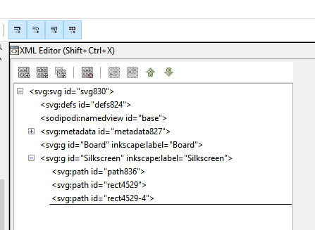
My beginners luck has just failed. I have created a shaped pcb board in Inkscape. I have the main board on layer “Board”. filled but no Stroke. Then on layer “Silkscreen” I have the same shape but no fill and Stroke set. The page is set to the same size as the objects. I then checked the XML data and I have the id’s set to Board and Silkscreen. It loads into Fritzing as a custom shape, but error messages come up saying there is no Silkscreen layer. There is. So I press OK to use the board anyway. Then another box about cutouts. OK to that too. The board comes up on screen as normal.
So I then try to export to OshPark and I get an error to say:
Removed empty file “iSpindle V6.1/ispindle v6_pcb1_18490250_contour.gm1”.
I can’t find a board outline file.
The XML data is below
Ay ideas why it isn’t loading properly?
If you could upload the SVG I would be happy to have a look.
If your board does have holes in it look at tip number 3 Inkscape Tips and Tricks
Last thing that may or may not have any effect is I have always used lower case names silkscreen not Silkscreen. I can not say it is an issue but it was the first thing I noticed when I read your post.
Not sure that the forum uploaded the svg file. so posted it on Sabercat just in case.
You have two groups:
Board which should contain the board as a solid in green. But in your case it was blank.
In your silkscreen you have three paths.
path836
rect4529
rect4529-4
path836 is a slightly smaller version of the next paths and should be deleted (I think).
rect4529 looks to be a solid green board layer which is your missing board layer.
rect4529-4 is the silkscreen outline you want in this layer. (I no longer use a silkscreen on my board outline as it tends to never line up perfectly with the milling).
So i have moved rect4529 out of the silkscreen and into the board group and renamed it board not Board. I then deleted path836 from the silkscreen group.
That still resulted in the complaint of no silkscreen layer and as I suspected it wanted silkscreen not Silkscreen.
![]() Right click and save as.
Right click and save as.
Also I should say if you have not found the xml editor in inkscape yet press (Shift Crtl X) to bring it up.
Many thanks. I see you have changed it to lower case silkscreen. I did wonder why in xml it looked like all the objects seemed to be on one layer. When editing I thought I moved the green board layer to the board and the other to the silkscreen. I’ll upload version and give it a go. Thanks for your help.
And the best news yet. It worked in OshPark.  Many thanks for your help.