So, I am super new to Embedded and anything hardware related (I’m in school for Software). I took a pretty basic Embedded course last semester and my semester project was to create a “Smart Window Blinds” controlled with Alexa.
I’m trying to order a PCB, but I’m concerned about a few things. Obviously on a Breadboard you have the power rails, on mine I have one rail with 12v and the other is 5v down from the linear voltage regulator.
• On my PCB design all the GND’S are routed to one GND pin on the Stepper motor driver (MP6500) and then that GND routes to the Capacitor connected to the voltage regulator…is this correct? Should they all route to the appropriate capacitor instead?
• I put all my GND traces on the bottom and then filled the bottom with copper, is this good? Should GND be connected to the GND “circles” that were placed on the PCB after I added the copper bottom?
• Same goes for some of the power pins. Like the SLP on the stepper driver is connected to the VMOT pin and then that routes to the 12v side of the voltage regulator, should SLP go directly to that as well? Should they both be connected to the Capacitor (like GND) instead of directly to the Voltage Regulator?
• Lastly, I do not understand schematics very well. I do not know if they are necessary in the production in PCB’s? Also, are the GND connections correct on the Schematic?
Sorry, I know this is a lot! Please be nice, I’m very new lol.
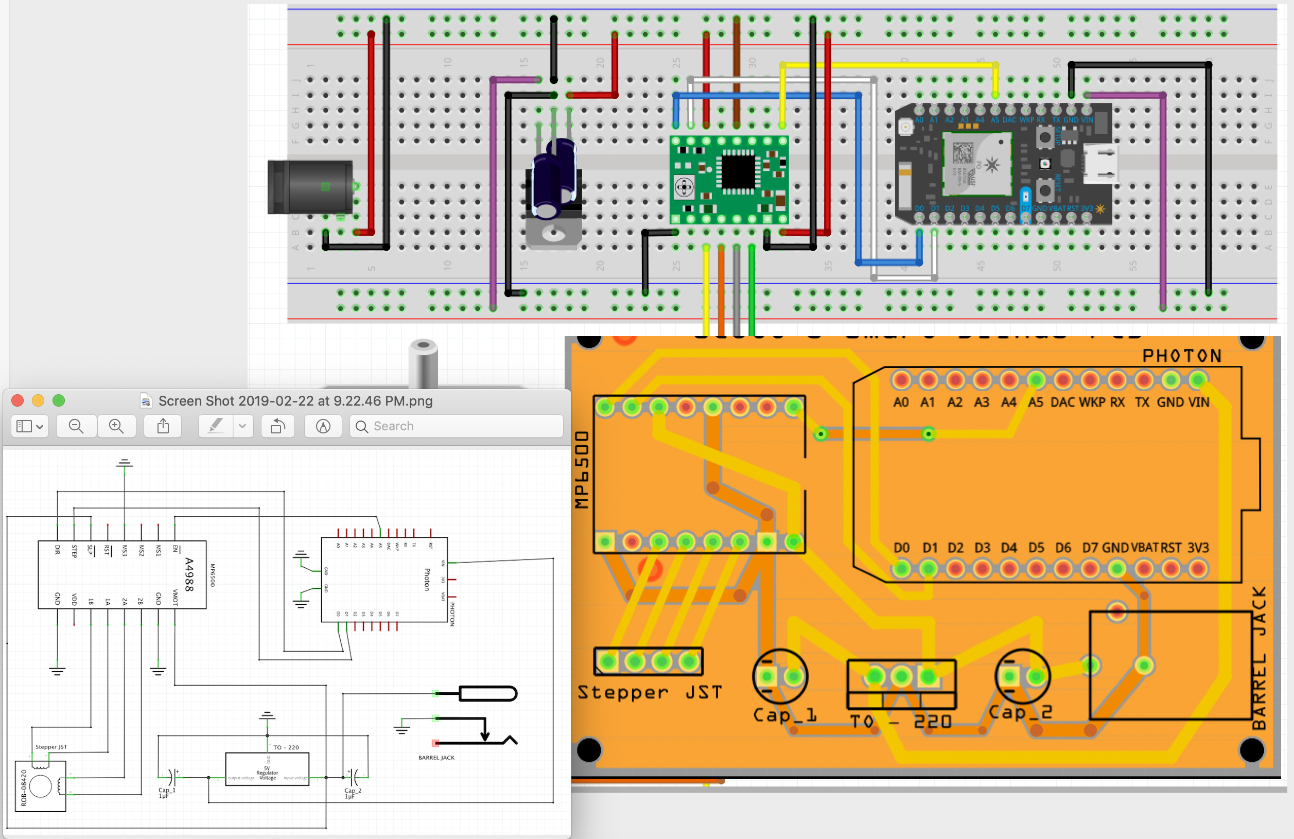
Below are my Breadboard, Schematic, and PCB design. (Actually I can only put one pic in a post)
Either way should be fine. What you want to avoid is having two paths to a single ground point such as one trace from the capacitor and another trace the runs across the board on a separate path then rejoins the ground to the stepper motor and I don’t see that here. You can upload the entire sketch (the .fzz file) to the forum then we can download it and poke at it for you. First next step is to run DRC (in pcb view, Routing->design Rules check), this will check the clearances on your board, I doubt it is going to complain but try it anyway. After that you want to export the gerber files (which the board is made from) and check them in one of the gerber viewer programs (I use gerbv from the open source geda project) . Sometimes the board looks fine in Fritzing, but has troubles translating in to gerber format. The gerber is what they will produce the board from so if it looks ok then you are probably good to go.
uploading the sketch is likely the best bet here. It think you are probably seeing solder relief points (as solid sheet of copper is hard to solder things to so it creates islands to allow easier soldering) but its hard to say from the picture. Your power routing looks fine, there is a wide trace to the microprocessor and a separate wide trace to the motor driver / moter (which are likely to cause current spikes that may bother the micro controller). The two traces is the best way to deal with that.
The gerber files are all that are required to cut the board, they don’t care about the schematic that is for you. The grounds look fine, a couple of them are technically upside down, but they won’t care. everything with the ground symbol attached happily attaches to the ground net. As long as all the connections are green (again hard to see in photos) it should be fine. Compared to a request for a new part this isn’t so much . If it runs on the breadboard it should run fine on the board.
Advise like this is easy, making parts for people generally takes way more time, and learning to make parts takes even more (which is why we tend to make parts for people who only need one or two).
I uploaded the file. I mainly wasn’t really sure what those “red circles” were and from what I could gather they are ground fills. So I wasn’t really sure if I needed/should connect the GND pins to them or just leave them where they are?
Sorry, I just thought of another question. Looks like one of these GND pins should connect to the 5V side. Should I connect it to the GND of the Capacitor or the GND of the Voltage regulator itself?
I read somewhere that your power and GND traces should be larger that’s why they’re wider. So I’m assuming I should just keep everything at the default 24 mil?
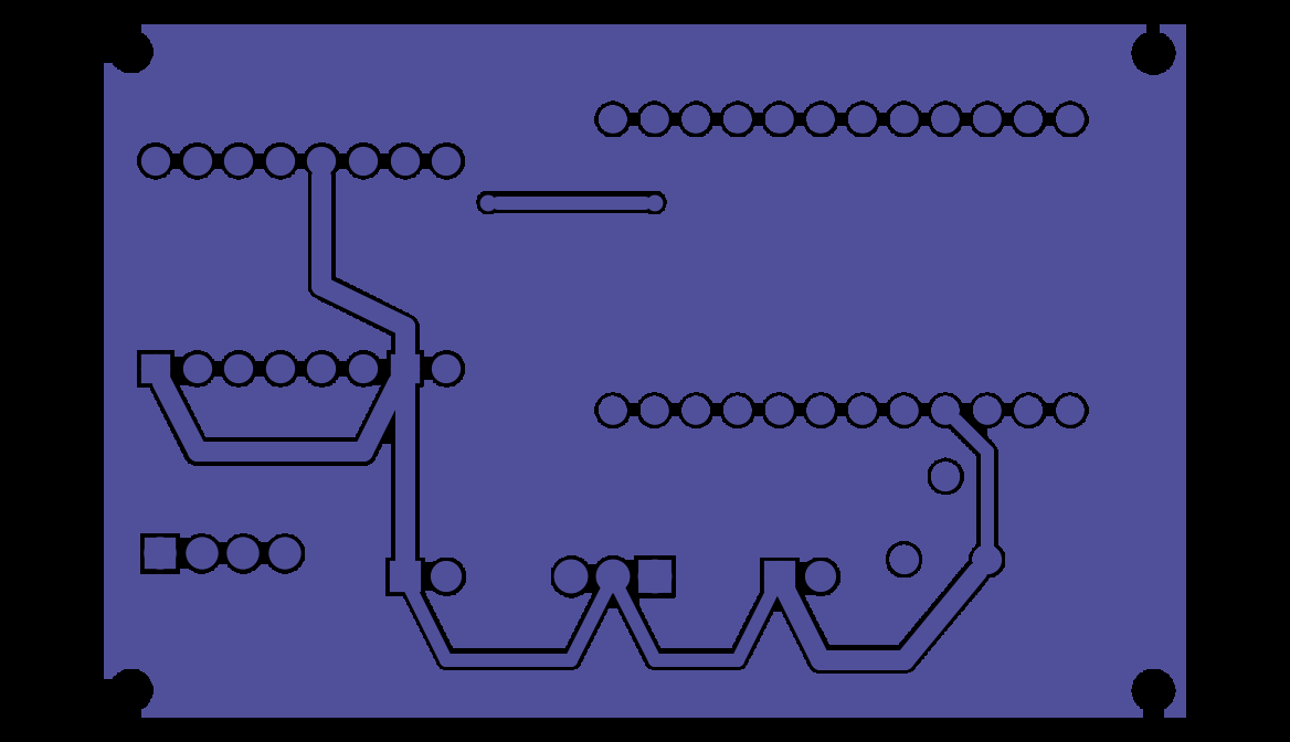
while I’m well out of my area of expertise here (I don’t do boards all the much), you look to have gotten a copper fill rather than a ground fill. That means the fill is isolated (not what you want). Here is the copper bottom from the gerbv display after exporting the gerber files (file->for production->extended gerber) displayed by gerbv:
You see the fill is completely isolated. You need to set ground seeds, but I don’t know enough about it to tell you how. Hopefully one of our pcb aware folks will provide an answer.
No, wide traces on power are better. The issue won’t likely come up in this small a board, but is voltage drop due to resistance in the trace which increases with current flow. You have both short traces (lower resistance, less of an issue) and relatively low currents. The logic circuits typically have a low threshold value of about .7V, so even a small voltage difference in ground due to high current flow can reduce the low level enough to cause hard to find occasional errors. To beat that you want to keep the high (or in this case higher but not very high ) ground path separate from the logic ground (which draws very little current normally) and you have done that. It looks to me like all you need is to get the ground fill attached to ground (and if you can’t, it likely isn’t really needed anyway) and you should be good to go. Except while looking at the ground pins on the motor driver I noticed a fatal error. You don’t have any connection to VDD (the logic power supply) on the motor driver (pin 11 one up from the ground on the bottom, shown in the part as “flt” but on the pololu connection diagram as VDD which needs to go to 5V to power the logic section of the motor driver.
As well there is a separate ground connection for the logic (as opposed to the higher current motor ground) that should connect like this (I just routed quickly with standard size traces, although this is all low current and shouldn’t matter much, plus the ground fill needs to be redone.
No. I’m happily retired after working for many years, and now do what I want. For the last couple of years that has been Fritzing, Making parts such as the motor driver or photon for Fritzing is challenging to say the least (it took me around a year and a lot of help from folks in here to get good at it). I’m also currently trying to restart development on Fritzing (which has currently stalled) so it doesn’t die.
I think you just right-click on the part pin in PCB and set GND seeds. You can click on a GND pin and it will turn yellow, and that way you know what pins to set.
Not that it matters in this case because the frequency in this is too low, but with traces you try to not make corners sharper than 45º.
The convention in SCH drawing is that all inputs are on the left, outputs on the right, GNDs always point down, and "+"s are always above.
Hey Peter, first I can’t thank you enough! I greatly appreciate you taking the time to answer all my questions!!!
So I’m actually using the stepper motor driver MP6500 from Pololu. I couldn’t find the exact fritz part for it, but the A4988 is exactly the same size and Pins are relatively the same except for VDD. On the MP6500 the VDD is the SLP pin, the FLT pin on the MP6500 is different I guess it’s for overcurrent protection. Thanks for looking out though!
So I need a ground fill on the bottom instead of a copper fill, but I don’t need to worry about the ground seeds?
You have a copper fill on the bottom, you need a ground fill. The copper fill fills all the copper unused by traces but doesn’t connect to any net (such as ground). So while there is a copper fill there, it isn’t touching any traces and is entirely isolated (it is not ground either). The ground fill will cause the fill to attach to any grounds it finds, but I’m unclear on where you put them. I’m hoping someone familiar with ground fills will answer. You could just experiment with ground fills or search for ground fill in the forum search tab as it has come up before several times.
Yes, but you need the ground seeds to create the ground fill so you do need to use them.
I’m so sorry Peter, if you’re still around, I have one more question.
After reading this I looked more closely and it seems I have kept the Stepper motor driver Logic and VMOT ground pins separate, but not sure if they’re correctly separated…It’s kind of hard to tell which of the Capacitors connected to the Voltage regulator are the 12v or 5v GND. Or does it not matter as long as they’re just separate?
Meaning as long as I keep one capacitor all connected to 12V GND pins and the other Cap all connected to 5v GND pins, it doesn’t actually matter which of those it is right?
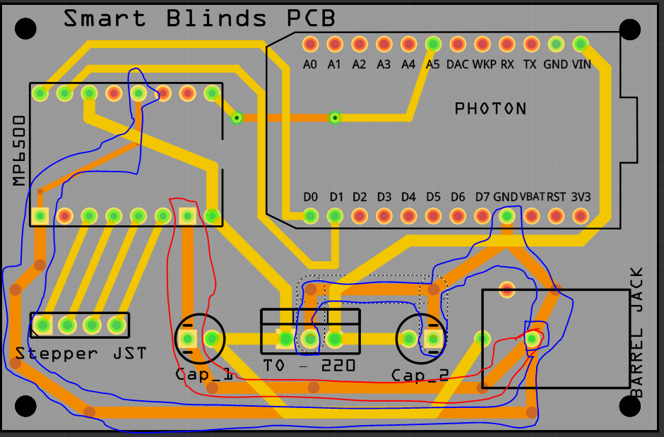
Assuming your board looks the same, it would be better to route the ground furthest to the left (the logic ground) directly to the ground on the micro, looking at it moving the ground on the 5V filter capacitor would be a good bet too. As well the i2 input wants to be to logic ground not motor ground (which may get high enough to change the logic level with bad results.) I deleted the ground fill to make the routing more obvious:
The basic idea is the logic ground and filter cap are completely separate from the motor current path (which they aren’t at present). In the layout above all of the 5V filter cap ground, the logic ground from the motor controller and the ground to the 5V filter capacitor all join at the microprocessor ground pin (all of them are low current.) The motor current goes on a different path where voltage drops won’t affect the logic signal levels. It probably won’t matter in this case but would with a higher current motor. Did you get the ground seed issue worked out?
Ok, I think I understand what you mean, but have a couple “quick” questions. Are the Capacitors backward…“Cap_1” is connected to the Output of the Voltage Regulator which would be the 5v and “Cap_2” is connected to Input of the Regulator, which would be 12V, right?
It looks like you connected the Barrel Jack ground directly to the Voltage Regulator, and then “Cap_2” to the GND of the Micro (Photon), I’m assuming that is what you mean by keeping the logic ground and filter Cap separate, right? The GND from the Micro (Photon) shouldn’t still be connected to the Barrel Jack GND though right, since that is 12V…? I took your changes and flipped the Voltage regulator. If you get a chance could you take a look let me know what you think? The only thing I’m unsure about is “Cap_2” which is the 5V side and that it’s no longer connected to the voltage regulator ground.
Wow, this is more complicated than I thought it would be! haha
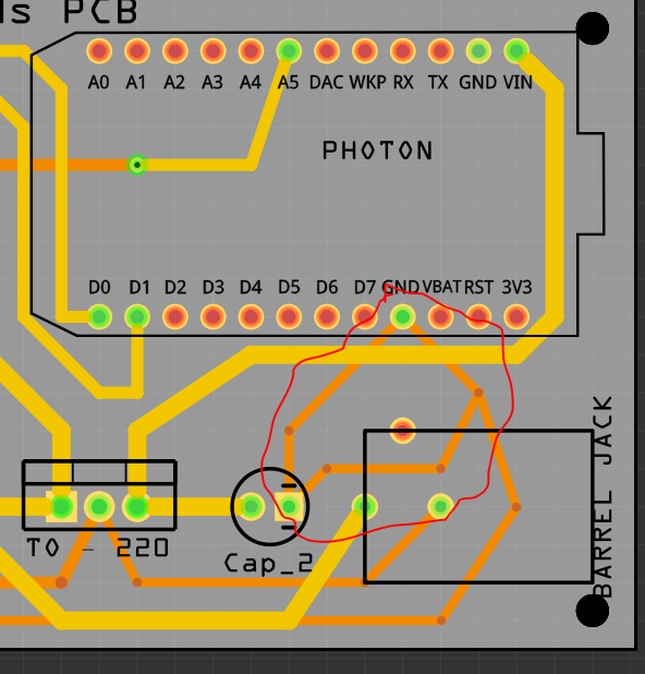
In this ugly picture the logic ground is in drunken blue. The ground pin of the barrel connector is the system common ground (with a blue sort of circle around it). The high current path to the motor is in the red circle. The issue we are trying to solve is that at the red pin of the motor driver board (referred to the blue circled barrel jack ground) up to a few hundred millivolts of difference due to the resistance of the traces and the typically large current draw of motors may occur. The logic ground path (from the same initial ground point) is drawing almost no current and won’t have any voltage drop, meaning that the logic levels when low will really be low, not approaching (or exceeding) the low logic threshold which is typically 0.7 volts. The motor doesn’t care about a voltage drop in its ground lead, the logic does. I also boosted the trace size on all the grounds just because you have the space and bigger is better. I also came straight out of the pins to get maximum separation and moved the ground for the voltage regulator on to the logic ground path rather than the motor path. It to won’t be drawing that much current. Essentially the blue circled pins on the motor driver may be up to a couple of hundred millivolts lower than the red circled pin on the motor driver depending on how much current the motor draws. With this configuration that doesn’t matter.
both your original board pass drc (in pcb view routing->design rules check) so clearance probably wasn’t an issue anyway but more clearance is better. As well this is something you don’t want to do:
the two parallel connections in ground can cause voltage differential due to different path resistance which can cause problems. Any point in the ground system should have only one connection to any other point in the ground system to avoid that.
My only question (and I’ll leave you alone after this) is why have both the logic and motor ground connected to the Barrel Jack ground? That’s 12v input, so shouldn’t the logic ground come from the 5v Capacitor ground?
It’s so much easier on a breadboard when you have different power and ground rails! Haha. I never really thought about the ground and power too much in a more permanent situation. It’s confusing!
The barrel jack is the initial source of ground, any point of ground that isn’t on the high current path (and thus subject to voltage drop) would do, the trick is to make sure the source of ground for the logic is somewhere that isn’t subject to a voltage drop due to high current. While we like to think of ground being ground and all the same, when dealing with high current and resistance in wire or traces, that isn’t correct. In this case this may be over kill, but better to have overkill than logic that only works most of the time. No need to limit your questions, I have time, and other people learn by reading this as well since it applies in lots of cases.