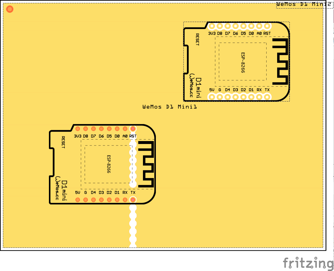
Used Wemos D1 mini witn “male below”. Copper protection areas are rotated 90 degrees.
I have project on which I spent many hours, I would like to avoid hacking and placing second variant if Wemos to actually “trick” Fritzing, because replacing part would result in recreating all connections. Any suggestions how to fix that without losing routed connections?
Which part are we talking about? Parts search (on 0.9.3 Windows) finds two Wemos D1 mini parts (but I see v.1 is marked obsolete) so I assume we are talking v2, but it only seems to have male above and female above, I don’t see a male below option on either part (which may mean I’m looking at the wrong part). If it is indeed unhappy about translate (and I don’t blame it I usually dislike them as well) it should be easy enough to fix. I’ll start by having a look at the v2 part and see what I see. Edit: I don’t think I’m on the correct part as the v2 seems to work fine as far as I can see in the gerbers with gerbv I don’t get the white circles (although I may not be setting things correctly). There only seem to be a translate in the silkscreen layer the rest is clean. Ok, found the source on github which does have a few more translates. I’ll poke at that …
There is a male below (all 4 of them actually) in the github repository he referenced. The male below in there exhibits the error reported (the pads are in a straight line). I’m almost finished manually translating it (it is really messed up! Its scaled down something like 13 to 1 (i.e the whole part fits in a single .1 square when all the translates are removed) and so is being somewhat exciting to fix …
The error was reported 6 months ago and he didn’t fix it.
From what I see all the parts are the same except for the pins, so it wouldn’t be hard to get the PCB svg from the other part and do a straight import, or mod and import, because the other parts work fine. It should be 5 min, do you want me to do it.
That would be great. I will test the updated part as soon as you got something.
And while you’re at it: could you also check the drill hole sizes? They seem to be very small (< 1mm) on the working parts.
Go File/Export/for Production/Extended Gerber, and save the file. In there is drill.txt, and when opened the hole sizes are in order of groups below, and the groups are the positions of holes. Download Gerbv and you can actually see the holes. You can also see if there are Gerber errors, like the pins on that part.
I measure 0,035 inch on the working D1 mini parts. The broken ones indeed have 0.057.
So when copy & pasting the footprints one should take care that the holes get the right sizes. Or am I missing something here?
Header pins are 0.024", I would be inclined to stick with 0.035" - that’s probably the difference between V1.0 and V2.0 - for the greater shear strength.
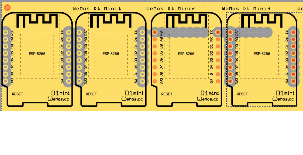
Well it looks like all the parts have faults.
V1.0 is dead because the produced Gerber is wrong and the holes are too big. Basically it’s obsolete and should be discarded.
V2.0 isn’t perfect because it doesn’t link when placed on a BB, and the connectors are hollow instead of red centre in PCB view, and SCH pins should also be red.
The V2.0 will work, and the only difference between 2 - V2.0s parts is the BB svgs. As I quick fix I can put the v1.0 BB svg into a new part to made from a v2.0, which will still have the other faults, and call it male below, but it will be exactly the same as male above in PCB view because they all use the same svg. In my opinion just use male above, as the PCB views are exactly the same.
Am I missing something here… I have three versions “Female Above, Male Above”, and the one I just modified “Female Above - Male Pins”, and they all work correctly in my FZ. What needs to be modified???